»  Categories   »      Thermal Shock Chamber   »    Environmental Chamber   »    Chamber / Oven   »    Environmental  

image enlarge

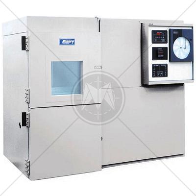
Tenney Thermal Shock Test Chamber -73°C to 200°C

Description

The Tenney Thermal Shock Chamber is a standalone thermal shock chamber with 0.25 cubic feet to 8 cubic feet carriage capacity. It's designed to accommodate pilot runs and smaller or bigger production quantities of sophisticated, discrete components.

Features

  • Open-air low mass nichrome wires
  • Ceramic insulators
  • Three zone types with a hot/ cold/ hot compartment setup
  • Cascade refrigeration system with TEV control and two semi-hermetic compressors
  • Vapor-tight interior liners made of 100% continuously welded stainless steel
  • Fully automatic, PID, chamber control through alpha-numeric display
  • Horizontal or vertical configurations
  • Door switch
  • Limit switch
  • Dual carriage transport system with stainless steel wire mesh basket

Performance

  • Temperature range:
  • Hot Chamber: +40°C to +200°C
  • Cold Chamber: -73°C to +40°C
  • Uniformity:  1.0° of Setpoint

Controller – Watlow 942

  • RTD for temperature measurement
  • Dual outputs
  • Auto-tuning control with 24-step program capability    
  • Simple single or fixed set point operation
  • 100 ohm platinum RTD sensor
  • Heat & cooling control, and boost cooling outputs

Specifications

Carriage Capacity
in. (cm)

Product Load

Refrigeration

Heat

Dimensions
W x H x D in. (cm)

Model

Wt lbs.

Ft3

W x H x D

LBS.

HP

KW

Horizontal Model

Vertical Model

TSJR Model (Air Cooled)

.25

10.5 x 6 x 6.125 
(26.7 x 15.2 x 15.6)

3

1/2 + 1/2 + LN2

2.5/.5

63 x 41 x 22 
(160 x 104.1 x 55.9)

Not Avail.

TSJR

700

TS2 Models - Two Zone: Hot/Cold (Water Cooled)

2

15 x 15 x 15 
(38.1 x 38.1 x 38.1)

15

4 + LN2

9/2

88 x 57 x 74 
(223.5 x 144.8 x 188)

89 x 72 x 58 
(226.1 x 182.9 x 147.3)

TS2.02.04B

3700

2

11

10

TS2.02.10

4000

8

25 x 23 x 25 (V) 
(63.5 x 58.4 x 63.5)
OR
23 x 25 x 25 (H) 
(58.4 x 63.5 x 63.5)

35

6 + LN2

21/4

99 x 75 x 88 
(251.5 x 190.5 x 223.5)

97 x 89 x 75 
(246.4 x 226.1 x 190.5)

TS2.08.06B

4200

8

35

30

TS2.08.30

4700

TSD Models - Dual Load: Hot/Cold/Hot (Water Cooled)

Carriage Capacity

Product Load

Refrigeration

Heat

Dimensions
W x H x D in. (cm)

Model

Wt lbs.

Ft3

W x H x D

LBS.

HP

KW

Horizontal Model

Vertical Model

2

15 x 15 x 15 
(38.1 x 38.1 x 38.1)

28

4 + LN2

18/2

129 x 88 x 53 
(327.7 x 223.5 x 134.6)

88 x 57 x 74 
(223.5 x 144.8 x 188)

TSD.02.04B

4200

2

18

10

140 x 88 x 53 
(355.6 x 223.5 x 134.6)

TSD.02.10

4500

8

25 x 23 x 25 (V) 
(63.5 x 58.4 x 63.5)
OR
23 x 25 x 25 (H) 
(58.4 x 63.5 x 63.5)

60

6 + LN2

42/4

156 x 88 x 72 
(396.2 x 223.5 x 182.9)

99 x 75 x 88 
(251.5 x 190.5 x 223.5)

TSD.08.06B

4700

8

56

30

185 x 80 x 83 
(469.9 x 203.2 x 210.8)

TSD.08.30

5200

Standards

CISPR
CISPR 11
CISPR 14 - 1
CISPR 14 - 2
CISPR 14 - 2
CISPR 16 - 1
CISPR 16 - 2
CISPR 16 - 3
CISPR 16 - 4
CISPR 22
CISPR 24
IEC
IEC/TR EN 61000 - 1 - 1
IEC/TR EN 61000 - 2 - 1
IEC/TR EN 61000 - 2 - 3
IEC EN 61000 - 3 - 2
IEC EN 61000 - 3 - 4
IEC/TC EN 61000 - 3 - 5
IEC EN 61000 - 4 - 2
IEC EN 61000 - 4 - 3
IEC EN 61000 - 4 - 4
IEC EN 61000 - 4 - 5
IEC EN 61000 - 4 - 6
IEC EN 61000 - 4 - 7
IEC EN 61000 - 4 - 8
IEC EN 61000 - 4 - 9
IEC EN 61000 - 4 - 11
European
EN 50 081 part 1
EN 50 081 part 2
EN 55 011
EN 55 013
EN 55 014
EN 55 015
EN 55 020
EN 55 022
EN 55 024
EN 50 082 part 1
EN 50 082 part 2
EN 50 093
American
FCC Part 15
MIL-STD - 461E