»  Categories   »      Reach-In Test Chamber   »    Environmental Chamber   »    Environmental   »    Chamber / Oven  

image enlarge

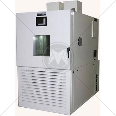
Tenney ETCU Cycling Test Chamber -70°C to 200°C

Description

ETCU Series Temperature Humidity Cycling Chambers

The Tenney ETCU Ultimate Series Temperature Humidity Cycling Chamber features scroll compressor technology that provides quiet operation, fast transition rates, and reliable operations.

The chambers incorporate a ceiling plenum to diffuse conditioned air vertically through the chamber. The top to bottom air circulation guarantees stable and consistent performance over the testing period.

Multiple heating and cooling systems are available, as well as a diverse list of options that together will create the chamber to accommodate your specific application.

Features

  • NEC compliant wiring
  • Scroll compressors on all standard models
  • Non-corroding parts on all humidity capable units
  • Low water protection
  • Open-air low mass nichrome wire heating elements supported by ceramic insulators
  • Single or cascade type refrigeration system
  • Vapor-Flo II Humidity Generator (when humidity system is employed)
  • Dehumidify coil
  • Vertical air flow system generated by centrifugal blower wheels
  • Interior chamber made of stainless steel insulated by fiberglass insulation and foam insulation

Performance Temperature ranges

  • With Single Stage Refrigeration: - 35° to + 200° C, +/- 0.5 deg. after stabilization
  • With Cascade Refrigeration System: - 73° to + 200° C, +/- 0.5 deg. after stabilization
  • Standard Humidity Range: 20% to 98% RH in the dry bulb range from +20° to +85° C, limited by a dewpoint of +3°C

Controller - VersaTenn V Controller

  • Two channel type controller
  • Auto/ manual control
  • Pentium class processor
  • 8 MB flash disk on chip storage
  • USB flash disk port
  • RS-232 communications
  • Color LED touch screen interface with real-time graphic displays
  • Microsoft Windows CE Operating System
  • Latest software developments in environmental test chamber control
  • RTD sensor for temperature measurement
  • Dry capacitance type humidity sensor for humidity measurement
  • Near infinite number of programs and steps
  • 10 temperature control outputs, 5 humidity control outputs, and 6 event outputs
  • Alarm output for each channel

Specifications

Model

ETCU–09

ETCU–16

ETCU–30

ETCU–64

Interior Volume

9 cu. ft.
256 liters

16 cu. ft.
460 liters

30 cu. ft.
850 liters

64 cu. ft.
1,812 liters

Interior Dimensions
W x D x H - inches (mm)

24 x 25 x 26
(610 x 635 x 660)

36 x 26 x 30
(914 x 660 x 762)

40 x 36 x 36
(1016 x 914 x 914)

48 x 48 x 48
(1219 x 1219 x 1219)

Exterior Dimensions
W x D x H - inches (mm)

34 x 73 x 78
(864 x 1854 x 1983)

46 x 74 x 82
(1169 x 1881 x 2084)

50 x 87 x 88
(1271 x 2211 x 2237)

58 x 99 x 100
(1474 x 2516 x 2542)

Nominal Horsepower

3.5 x 3.5

6 x 6

10 x 10

3.5 x 3.5

6 x 6

10 x 10

3.5 x 3.5

6 x 6

10 x 10

15 x 15

3.5 x 3.5

6 x 6

10 x 10

15 x 15

Rated Horsepower

2.5 x 2.5

5 x 5

10 x 10

2.5 x 2.5

5 x 5

10 x 10

2.5 x 2.5

5 x 5

10 x 10

15 x 15

2.5 x 2.5

5 x 5

10 x 10

15 x 15

Compressor Type

Scroll

Scroll

Scroll

Scroll

Noise (dBA)

Heating

60

60

60

60

60

60

60

60

60

60

60

60

60

60

Cooling

68

75

75

68

75

75

68

75

75

75

68

75

75

75

Heating Elements (kW)

230/460

6

12

12

6

12

12

6

12

12

24

6

12

12

24

208V

4.5

9

9

4.5

9

9

4.5

9

9

18

4.5

9

9

18


Model

ETCU–09

ETCU–16

ETCU–30

ETCU–64

Cooling Rate (min)

190°C to -65°C

49

34

14

78

36

19

155

76

31

20

256

125

52

42

71°C to -65°C

36

26

11

40

28

15

119

59

26

17

197

97

44

33

85°C to -40°C

27

18

8

32

20

12

95

42

21

12

157

69

36

24

Heating Rate (min)

-65°C to 190°C

35

16

16

32

22

22

60

30

30

20

110

53

53

27

-65°C to 71°C

17

8

8

14

11

11

27

13

13

10

45

23

23

13

-40°C to 85°C

16

8

8

12

10

10

27

13

13

11

45

23

23

14

Water Cooled

Y

Y

Y

Y

Y

Y

Y

Y

Y

Y

Y

Y

Y

Y

Air Cooled

Y


Y

Y


Y

Y


Y

Y


208/230V 1 Ph

Y

N/A

N/A

Y

N/A

N/A

Y

N/A

N/A

N/A

Y

N/A

N/A

N/A

208/230V 3 Ph

Y

Y

N/A

Y

Y

N/A

Y

Y

N/A

N/A

Y

Y

N/A

N/A

460V 3 Ph

Y

Y

Y

Y

Y

Y

Y

Y

Y

Y

Y

Y

Y

Y

Air Delivery (Blower HP)

.5 HP

(2) .5 HP

(2) .75 HP

(2) .75 HP

Airflow (CFM)

750

1600

1600

1600

Temp Unif. (Std Dev/9 Pt)

+/-0.5°C/+/-1°C

+/-0.5°C/+/-1°C

+/-0.5C/+/-1°C

+/-0.5C/+/-1°C

Temp Control

+/-0.3°C

+/-0.3°C

+/-0.3°C

+/-0.3°C


Single Stage Refrigeration Temperature Range: -35°C to 200°C

Performance is based upon an empty chamber operating at 24°C (75°F) ambient air and may vary slightly at other ambient temperatures. Voltages below those listed may affect performance. All performance data is for 240 or 480V / 60Hz operation.

Liquid Nitrogen is available as an option on all systems. When Liquid Nitrogen is provided, the heater KW is automatically upgraded to the maximum for that chamber size. Consult factory for current draw of any Liquid Nitrogen equipped chambers.

Airflow circulation is based on blower wheel performance curves. Actual circulation rate will vary depending on the cooling option selected.

Temperature uniformity Standard deviation from the mean, measured at –25°C and 100°C. 9 Point: Uniformity measured in accordance with ASTM E145 section 4 at temperatures of –25°C and 100°C.

Test chamber performance may be affected by the addition of certain optional accessories.

Chamber operation utilizing 50Hz power utility will derate performance approximately 17%

It is Thermal Product Solutions' policy to constantly improve quality, features and performance. Thermal Product Solutions reserves the right to change specifications without notice.

Standards

CISPR
CISPR 11
CISPR 14 - 1
CISPR 14 - 2
CISPR 14 - 2
CISPR 16 - 1
CISPR 16 - 2
CISPR 16 - 3
CISPR 16 - 4
CISPR 22
CISPR 24
IEC
IEC/TR EN 61000 - 1 - 1
IEC/TR EN 61000 - 2 - 1
IEC/TR EN 61000 - 2 - 3
IEC EN 61000 - 3 - 2
IEC EN 61000 - 3 - 4
IEC/TC EN 61000 - 3 - 5
IEC EN 61000 - 4 - 2
IEC EN 61000 - 4 - 3
IEC EN 61000 - 4 - 4
IEC EN 61000 - 4 - 5
IEC EN 61000 - 4 - 6
IEC EN 61000 - 4 - 7
IEC EN 61000 - 4 - 8
IEC EN 61000 - 4 - 9
IEC EN 61000 - 4 - 11
European
EN 50 081 part 1
EN 50 081 part 2
EN 55 011
EN 55 013
EN 55 014
EN 55 015
EN 55 020
EN 55 022
EN 55 024
EN 50 082 part 1
EN 50 082 part 2
EN 50 093
American
FCC Part 15
MIL-STD - 461E