|
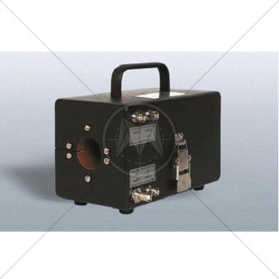
Impedance Matching Injection Probe.
The unique winding arrangement of this impedance matching probe provides step-up or step-down ratios with respect to either: 1) the source impedance of the connected generator, when used for injection, or 2) the load impedance of the connected receiver, when used for reception. This results in maximum power transfer into or out of the transformer winding formed by the cable bundle passing through the window.
Various EMI specifications require the injection of high level voltage or current pulses and the reception of low level voltage or current emissions using a toroidal transformer or coupling device around the interconnecting conductors of the subsystems/equipment being tested.
- The Type 9335-2 Multiple Impedance Coupling Device provides
- 1:1.0 voltage or current transfer
- 1:1.5 voltage step-up or current step-down
- 2:1.0 voltage step-down or current step-up
- 1:3.0 voltage step-up or current step-down
These ratios are selected by connecting to one of the four BNC connectors on the side of the Type 9335-2.
Standards
|
CISPR 11 |
|
CISPR 14 - 1 |
|
CISPR 14 - 2 |
|
CISPR 14 - 2 |
|
CISPR 16 - 1 |
|
CISPR 16 - 2 |
|
CISPR 16 - 3 |
|
CISPR 16 - 4 |
|
CISPR 22 |
|
CISPR 24 |
|
IEC/TR EN 61000 - 1 - 1 |
|
IEC/TR EN 61000 - 2 - 1 |
|
IEC/TR EN 61000 - 2 - 3 |
|
IEC EN 61000 - 3 - 2 |
|
IEC EN 61000 - 3 - 4 |
|
IEC/TC EN 61000 - 3 - 5 |
|
IEC EN 61000 - 4 - 2 |
|
IEC EN 61000 - 4 - 3 |
|
IEC EN 61000 - 4 - 4 |
|
IEC EN 61000 - 4 - 5 |
|
IEC EN 61000 - 4 - 6 |
|
IEC EN 61000 - 4 - 7 |
|
IEC EN 61000 - 4 - 8 |
|
IEC EN 61000 - 4 - 9 |
|
IEC EN 61000 - 4 - 11 |
|
EN 50 081 part 1 |
|
EN 50 081 part 2 |
|
EN 55 011 |
|
EN 55 013 |
|
EN 55 014 |
|
EN 55 015 |
|
EN 55 020 |
|
EN 55 022 |
|
EN 55 024 |
|
EN 50 082 part 1 |
|
EN 50 082 part 2 |
|
EN 50 093 |
|
FCC Part 15 |
|
MIL-STD - 461E |
| 