|
The CLA-050 and CL-150 absorbing clamps meet the CISPR 14 (EN 55014) section 6.11 requirements for measuring radio frequency power generated and fed to the EUT supply cable of household appliances, electri¬cal tools and similar apparatus.
The absorbing clamp consists of a calibrated ferrite current transformer operating in the frequency range of 30-1000 MHz and two groups of ferrite rings. The ferrite rings acts as absorbers of energy and stabilizes impedance. One set of ferrite rings surrounds the lead from the transformer to the EMI meter to minimize standing waves. The second group of ferrite rings surrounds supply cable from the equipment under test. These rings act as an absorber of energy and an im¬pedance stabilizer to isolate the equipment under test from the mains. These rings are made up of two halves. Therefore, the supply cable from the EUT can be placed inside the aperture of the rings.
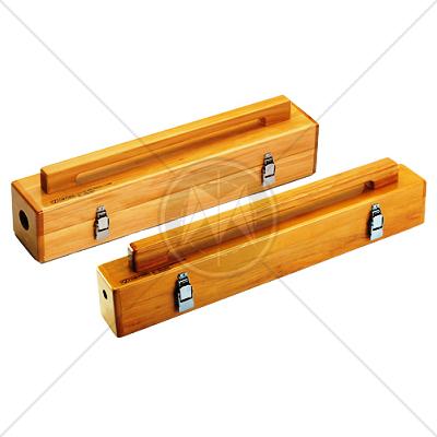
Two absorbing clamp models are available to accom¬modate the varying sizes of supply cables. The model CLA-050 can accommodate supply cable up to 10 mm (0.39 inches) in diameter and model CLA-150 can accept cables up to 32 mm (1.26 inches) diameter.
- Frequency Range - 30 - 1000 MHz
- Test to CISPR 14 (EN 55014) requirements
- Individual Calibration
Com-Power CLA-050 Application
Use of an absorbing clamp is a practical alternative to measurement of direct field strength from EUT supply cables.
During the test, the equipment under test is placed on a nonconductive table at least 40 cm from the nearest reflecting object. The EUT mains conductor is placed horizontally in a straight line for a distance sufficient to permit movement of the absorbing clamp to obtain the highest readings. The mains conductor is placed in the clamp surrounded by absorbing rings and the current transformer.
The standard requires the measuring instrument having a 50 Ohm input impedance. The power (P) measured using a 50 Ohm load is equal to the square of the voltage measured divided by 50. This can be expressed in decibels (dB):
P = Power
10 log P = 10 log V2/50 = 20 log V-10 log 50
10 log P = 20 log V - 10 log 50
IL = Insertion loss
Corrected reading: 10 log P = 20 log V - 17 dB + IL
The numerical value of P (power) expressed in dB (Pico watts across 50 Ohms) is found by subtracting 17 dB from the numerical value of V in dB.
|
Model
|
CLA-050
|
CLA-150
|
|
Frequency range
|
30 MHz - 1000 MHz
|
30 MHz - 1000 MHz
|
|
Maximum cable diameter
|
10 mm (0.39 inches)
|
32 mm (1.26 inches)
|
|
Aperture diameter
|
12.7 mm (0.5 inches)
|
34.9 mm (1.37 inches)
|
|
Connector
|
BNC (f)
|
BNC(f)
|
|
Dimensions (L x W x H)
|
627 x 114 x 144 mm
|
627 x 114 x 165 mm
|
|
24.7 x 4.5 x 5.7 inches
|
24.7 x 4.5 x 6.5 inches
|
|
Weight
|
5 kg (11.5 lbs)
|
9.5 kg (21 lbs)
|
Standards
|
CISPR 11 |
|
CISPR 14 - 1 |
|
CISPR 14 - 2 |
|
CISPR 14 - 2 |
|
CISPR 16 - 1 |
|
CISPR 16 - 2 |
|
CISPR 16 - 3 |
|
CISPR 16 - 4 |
|
CISPR 22 |
|
CISPR 24 |
|
IEC/TR EN 61000 - 1 - 1 |
|
IEC/TR EN 61000 - 2 - 1 |
|
IEC/TR EN 61000 - 2 - 3 |
|
IEC EN 61000 - 3 - 2 |
|
IEC EN 61000 - 3 - 4 |
|
IEC/TC EN 61000 - 3 - 5 |
|
IEC EN 61000 - 4 - 2 |
|
IEC EN 61000 - 4 - 3 |
|
IEC EN 61000 - 4 - 4 |
|
IEC EN 61000 - 4 - 5 |
|
IEC EN 61000 - 4 - 6 |
|
IEC EN 61000 - 4 - 7 |
|
IEC EN 61000 - 4 - 8 |
|
IEC EN 61000 - 4 - 9 |
|
IEC EN 61000 - 4 - 11 |
|
EN 50 081 part 1 |
|
EN 50 081 part 2 |
|
EN 55 011 |
|
EN 55 013 |
|
EN 55 014 |
|
EN 55 015 |
|
EN 55 020 |
|
EN 55 022 |
|
EN 55 024 |
|
EN 50 082 part 1 |
|
EN 50 082 part 2 |
|
EN 50 093 |
|
FCC Part 15 |
|
MIL-STD - 461E |
|