»  Categories   »      Benchtop Oscilloscope   »    Oscilloscope  

image enlarge

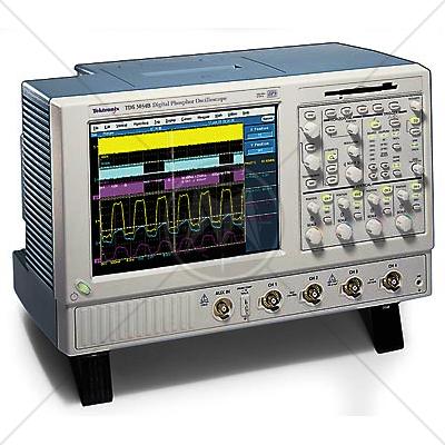
Tektronix TDS5052B 2 Channel 500 MHz Digital Oscilloscope 5 GSa/s

Description

The TDS5000B Series offers the industrys first easily customizable oscilloscope user interface. MyScope control windows is a revolutionary new feature that allows you to build your own control windows with only the controls, features, and capabilities that you care about and are important in your job. For the first time, you can pull all the functionality you need from all the various parts of the oscilloscope into one control window, effectively creating your own personalized toolbox of oscilloscope features. No longer do you need to search through menus for features or re-learn how to drive the oscilloscope after a break from the lab.

MyScope control windows enable you to spend your valuable time focused on the task at hand rather than navigating menus on your oscilloscope. And creating these custom control windows isnt a long drawn-out or complex process. They are easily created in a matter of minutes using a simple, visual, drag and drop process. Once created, these custom control windows are easily accessed through a dedicated MyScope button and menu selection on the oscilloscope button/menu bar, just like any other control window. You can make an unlimited number of custom control windows, enabling each person who uses the oscilloscope, in a shared environment, to have their own unique control window. Since the control windows are stored as files on the hard drive, they can easily be transferred to other TDS5000B Series oscilloscopes, or they can even be e-mailed to a co-worker around the world when the need arises. MyScope control windows will benefit all oscilloscope users, from eliminating the ramp-up time that many face when returning to the lab after not using an oscilloscope for a while, to the power user who can now operate far more efficiently. Everything you need is found in one control window rather than having to constantly navigate through menu after menu to repeat similar tasks.

Features

  • 500 and 350 MHz Bandwidth Models
  • 2 and 4 Channel Models
  • 5 GS/s Sample Rate
  • Up to 16 M Record Length
  • 100,000 wfms/s Maximum Waveform Capture Rate
  • MyScope™ Custom Control Windows Enhance Productivity
  • Right-Mouse-Click Menus for Exceptional Efficiency
  • OpenChoice® Platform with Windows 2000 Delivers Built-in Networking and Analysis
  • Small Footprint/Lightweight
  • 10.4 in. Bright Display
  • Suite of Advanced Triggers
  • Communication Mask Testing
  • Pass/Fail Limit Testing
  • Remote Viewing and Control
  • E-mail on Event
  • CD-RW Drive
  • Built-in Printer (Optional)
  • Interoperability with Tektronix Logic Analyzers
  • GPIB Controller

Tektronix TDS5052B Applications

  • Digital Design and Debug
  • Mask Testing for Telecomm/Datacomm/Video Standards
  • Investigation of Transient Phenomena
  • Power Measurements
  • Video Design and Debug
  • DVD, Jitter and Timing, Spectral Analysis
  • Automotive Electronics
  • Manufacturing Test
  • Electro-mechanical
  • Bio-medical
  • Industrial Control

Specifications

Vertical System


TDS5032B

TDS5052B / TDS5054BE

Input Channels

2

2/4

Analog Bandwidth (-3 dB) 5 mV/div - 1 V/div

350 MHz

500 MHz

Calculated Rise Time 5 mV/div (typical)

1.15 ns

800 ps

Hardware Bandwidth Limits

150 MHz or 20 MHz

Input Coupling

AC, DC, GND

Input Impedance, 1 MΩ

±1%

Input Impedance, 50 Ω

±1%

Input Sensitivity, 1 MΩ

1 mV/div to 10 V/div

Input Sensitivity, 50 Ω

1 mV/div to 1 V/div

Vertical Resolution

8-bits (>11-bits w/ averaging)

Max Input Voltage, 1 MΩ

150 V CAT I, ≤ 400 V peak. Derate at 20 dB/decade to 9 VRMS above 200 kHz

Max Input Voltage, 50 Ω

5 VRMS with peaks <±30 V

DC Gain Accuracy

1.5% with offset set to 0 V

Offset Range, 1 MΩ

1 mV/div - 99.5 mV/div ±1 V

100 mV/div - 1 V/div ±10 V

1.01 V/div - 10 V/div ±100 V

Offset Range, 50 Ω

1 mV/div - 99.5 mV/div ±1 V

100 mV/div -1 V/div ±10 V

Channel-to-channel Isolation for Any Two Channels at Equal Vertical Scale

≥100:1 at ≤100 MHz and ≥30:1 at >100 MHz up to the rated bandwidth

Timebase System

Timebase Range

200 ps/div to 1000 s/div

Timebase Delay Time Range

(s/div × 10) to 1000 s

Channel-to-channel Deskew Range

±75 ns

Timebase Accuracy

15 ppm

Delta Time Measurement Accuracy

(0.06/sample rate + 15 ppm × |Reading|)RMS

Trigger Jitter (RMS)

8 psRMS (typical)

Long Term Sample Rate and Delay Time Accuracy

±15 ppm over any ≥1 ms interval

Acquisition System


TDS5032B / TDS5052B

TDS5054BE

Real-time Sample Rates


   Channel (max)

5 GS/s

1 GS/s

   2 Channels (max)

2.5 GS/s

1 GS/s

   3-4 Channels (max)

--

1 GS/s

Equivalent Time Sample Rate (max)

250 GS/s

200 GS/s

Maximum Record Length per Channel with Standard Memory

8M/4M/--

8M/4M/2M

With Opt. 3M

16M/8M/--

16M/8M/4M

Maximum Duration at Highest Real-time Resolution (1 ch)


TDS5054BE

All Other Models

Time Resolution (single shot)

1 ns (1 GS/s)

200 ps (5 GS/s)

Max Duration with Standard Memory

8 ms

1.6 ms

Max Duration with Opt. 3M

16 ms

3.2 ms

Acquisition Modes

FastAcq Acquisition

FastAcq optimizes the instrument for analysis of dynamic signals and capture of infrequent events. Maximum FastAcq waveform capture rate is 100,000 wfms/s.

Sample

Acquire sampled values

Peak Detect

Captures narrow glitches (<1 ns) at all real-time sampling rates

Averaging

From 2 to 10,000 waveforms included in average

Envelope

From 2 to 2 × 10⁹ waveforms included in min-max envelope

Hi-Res

Real-time boxcar averaging reduces random noise and increases resolution

Waveform Database

Accumulates a waveform database that provides a three dimensional array of amplitude, time, and counts

FastFrame™ Acquisition

Acquisition memory divided into segments; maximum trigger rate >225,000 waveforms per second

Trigger System

Sensitivity

Internal DC Coupled

0.35 div DC to 50 MHz increasing to 1 div at rated bandwidth

External (auxiliary input)

400 mV from DC to 50 MHz increasing to 750 mV at 100 MHz

Main Trigger Modes

Auto, Normal, and Single

Trigger Sequences

Main, Delayed by time, Delayed by events. All sequences can include separate horizontal delay after the trigger event to position the acquisition window in time.

Standard Trigger Types

Edge, Glitch, Runt, Window, Width, Transition Time, Timeout, Pattern, Video, State, Setup/Hold

A Event and Delayed B Event Trigger Types


   A Event

All above types

   Delayed B Event

Edge

Communications-related Triggers (requires Option SM)

Support for AMI, HDB3, BnZS, CMI, MLT3, and NRZ encoded communications signals. Select among isolated positive or negative one, zero pulse form or eye patterns as applicable to standard

Trigger Level Range

Any Channel

±10 divisions from center of screen

External (auxiliary in)

±8 V

Line

Fixed at 0 V

Trigger Coupling

DC, AC (attenuate <60 Hz), HF reject (attenuate >30 kHz)

LF reject (attenuates <80 kHz) Noise reject (reduce sensitivity)

Trigger Holdoff Range

1.5 μs to 12 s maximum

Trigger Modes

Edge

Positive or negative slope on any channel or front panel auxiliary input. Coupling includes DC, AC, noise reject, HF reject, and LF reject.

Video

Trigger on NTSC, PAL, SECAM, analog HDTV, and non-standard video formats

Glitch

Trigger on or reject glitches of positive, negative or either polarity. Minimum glitch width is 1.0 ns with 200 ps resolution.

Width

Trigger on width of positive or negative pulse either within or out of selectable time limits ranging from 1 ns to 1 s with 200 ps resolution

Runt

Trigger on a pulse that crosses one threshold but fails to cross a second threshold before crossing the first again. Event can be time or logic qualified (logic on 4 channel models only).

Window

Trigger on an event that enters or exits a window defined by two user-adjustable thresholds. Event can be time or logic qualified (logic on 4 channel models only).

Timeout

Trigger on an event which remains high, low or either, for a specified time period, selectable from 1 ns to 1 s with 200 ps resolution

Transition

Trigger on pulse edge rates that are faster or slower than specified. Slope may be positive, negative or either

Setup/Hold

Trigger on violations of both setup time and hold time between clock and data present on any two input channels

Pattern

Trigger when pattern goes false or stays true for specified period of time. Pattern (AND, OR, NAND, NOR) specified for four input channels defined as High, Low or Don't Care.

State

Any logical pattern of channels (1, 2, 3) clocked by edge on channel 4 (channel 2 on TDS5032B/5052B). Trigger on rising or falling clock edge.

Comm (requires option SM)

Support for AMI, HDB3, B3ZS, B6ZS, B8ZS, CMI, NRZ and MLT3 encoded communication signals. Select among isolated positive or negative one, zero pulse form or eye patterns as applicable to standard.

Trigger Delay by Time

16 ns to 250 seconds

Trigger Delay by Events

1 to 10,000,000 Events

WAVEFORM MEASUREMENTS

Automatic Measurements

53 of which 8 can be displayed on screen at any one time

   Amplitude Related

Amplitude, High, Low, Maximum, Minimum, Peak to Peak, Mean, Cycle Mean, RMS, Cycle RMS, Positive Overshoot, Negative Overshoot

   Time Related

Rise Time, Fall Time, Positive Width, Negative Width, Positive Duty Cycle, Negative Duty Cycle, Period, Frequency, Delay

   Combination

Area, Cycle Area, Phase, Burst Width

   Histogram Related

Waveform count, Hits in box, Peak hits, Median, Maximum, Minimum, Peak to Peak, Mean (μ), Standard Deviation (σ), μ ± 1σ, μ ± 2σ, μ ± 3σ

   Communications Related

Extinction Ratio (abs, %, dB), Eye Height, Eye Width, Eye Top, Eye Base, Crossing %, Jitter (Pk-Pk, RMS, 6σ), Noise (Pk-Pk, RMS), Signal/Noise Ratio, Cycle Distortion, Q-Factor

Measurement Statistics

Mean, Min, Max, Standard Deviation, Population

Reference Levels

User definable for each of the eight measurements

Histograms

Vertical or horizontal with linear or log scaling

Gating

Isolate the specific occurrence within an acquisition to take measurements on

Cursors

Horizontal Bars, Vertical Bars, Waveform, and Screen

WAVEFORM PROCESSING/MATH

Arithmetic

Add, subtract, multiply, and divide waveforms.

Algebraic Expressions

Define extensive algebraic expressions including waveforms, scalars, user adjustable variables, and results of parametric measurements e.g. (Integral (Ch1-Mean(Ch1))*1.414*VAR1).

Math Functions

Average, Invert, Integrate, Differentiate, Square Root, Exponential, Log 10, Log e, Abs, Ceiling, Floor, Min, Max, Sin, Cos, Tan, ASin, ACos, ATan, Sinh, Cosh, Tanh

Frequency Domain Functions

Spectral magnitude and phase, real and imaginary spectra.

Vertical Units


   Magnitude

Linear, dB, dBm.

   Phase

degrees, radians, group delay.

Window Functions

Rectangular, Hamming, Hanning, Kaiser-Bessel, Blackman-Harris, Gaussian, Flattop2, Tek Exponential.

Limit Testing

Compare live waveforms against a known “golden” reference waveform with user defined vertical and horizontal tolerances.

DISPLAY CHARACTERISTICS

Display Type

10.4 in. Liquid crystal active-matrix color display

Display Resolution

640 horizontal x 480 vertical pixels

Waveform Styles

Vectors, Dots, Intensified Samples, Variable Persistence, Infinite Persistence

Display Format

YT, XY, XYZ

Color Palettes

Individual color palettes for Record View and FastAcq/WfmDB modes include Normal, Green, Gray, Temperature, Spectral, and User Defined

Standards

CISPR
CISPR 11
CISPR 14 - 1
CISPR 14 - 2
CISPR 14 - 2
CISPR 16 - 1
CISPR 16 - 2
CISPR 16 - 3
CISPR 16 - 4
CISPR 22
CISPR 24
IEC
IEC/TR EN 61000 - 1 - 1
IEC/TR EN 61000 - 2 - 1
IEC/TR EN 61000 - 2 - 3
IEC EN 61000 - 3 - 2
IEC EN 61000 - 3 - 4
IEC/TC EN 61000 - 3 - 5
IEC EN 61000 - 4 - 2
IEC EN 61000 - 4 - 3
IEC EN 61000 - 4 - 4
IEC EN 61000 - 4 - 5
IEC EN 61000 - 4 - 6
IEC EN 61000 - 4 - 7
IEC EN 61000 - 4 - 8
IEC EN 61000 - 4 - 9
IEC EN 61000 - 4 - 11
European
EN 50 081 part 1
EN 50 081 part 2
EN 55 011
EN 55 013
EN 55 014
EN 55 015
EN 55 020
EN 55 022
EN 55 024
EN 50 082 part 1
EN 50 082 part 2
EN 50 093
American
FCC Part 15
MIL-STD - 461E