»  Categories   »      CDN   »    EMC / EMI   »    Coupling / Decoupling (CDN)  

image enlarge

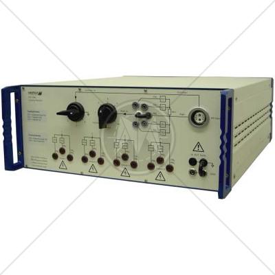
Haefely PCD 126A CDN Asymmetrical & Symmetrical Lines

Description

The PCD 126A is used for surge coupling of 1,2/50us - 8/20us combination wave impulses onto unshielded asymmetrical data and signal lines according IEC/EN standards. It is also used for surge coupling ring wave impulses onto both unshielded asymmetrical and symmetrical data and control lines according to IEC/EN standards. Up to 6.6 kV peak value are possible. Up to 4 wires can be tested simultaneously.

To obtain maximum flexibility only coupling elements are included in the PCD 126A. Decoupling circuits, which depends on the EUT to be tested, can be placed separately in the test setup.

Manual coupling path switching for common mode (longitudinal, line to earth) and differential mode (transversal, line to line) testing.

Default coupling elements are capacitors, breakdown avalanche diodes and gas arrestors. The coupling elements can be selected easily. The direct coupling output allows the customer to use his own coupling elements.
The PCD 126A can be used together with the impulse modules PIM 100 and PIM 110 from the Surge Platform and the PSURGE 4010. These provide all the programming functions required to perform IEC, ANSI and EN testing also without the need of a control computer.

Features

  • Combination wave 1,2/50us - 8/20us impulses
  • Serial resistor 40 Ohm included
  • Ringwave 100kHz impulses
  • Up to 4 wires can be tested
  • Signal Bandwidth up to some MHz
  • Manual coupling path selection

Applications

  • Unshielded asymmetrical data and signal lines
  • Unshielded symmetrical data and signal lines (ring wave testing only)
  • Industrial equipment
  • Other international requirements for combination wave and ring wave impulses on asymmetrical data- and control lines

Specifications

Impulse shapes

Combination wave 1,2/50us, 8/20us

Ring wave 100kHz

Z = 2 Ohm

Z = 12 Ohm, 30 Ohm and 200 Ohm

Impulse amplitude

max. 6.6kV

for both impulse shapes

Serial Resistor

1 x 40W

for testing according IEC 61000-4-5

Coupling elements

Capacitor 0.5uF / 3uF

Avalanche breakdown diode (ABD)

Avalanche breakdown diodes (ABDs)

Gas arrestors

Direct

for asymmetrical lines, both impulse shapes

for asymmetrical lines, both impulse shapes

for symmetrical lines, ring wave only

for symmetrical lines, ring wave only

for customer specific coupling elements

Voltage on EUT lines

Max. 375VDC or 265VAC,RMS

Max. 72VDC or 50VAC,RMS

with capacitors as coupling elements

with ABDs or gas arrestors as coupling

elements

Signal bandwidth for the EUT signals

up to > 1kHz

up to > 1MHz

up to > 10MHz

with capacitors as coupling elements

with ABDs as coupling elements

with gas arrestors as coupling elements

Dimensions

45 x 19.5 x 57 cm (w x h x d)

Weight

approx. 12 kg net

Standards

CISPR
CISPR 11
CISPR 14 - 1
CISPR 14 - 2
CISPR 14 - 2
CISPR 16 - 1
CISPR 16 - 2
CISPR 16 - 3
CISPR 16 - 4
CISPR 22
CISPR 24
IEC
IEC/TR EN 61000 - 1 - 1
IEC/TR EN 61000 - 2 - 1
IEC/TR EN 61000 - 2 - 3
IEC EN 61000 - 3 - 2
IEC EN 61000 - 3 - 4
IEC/TC EN 61000 - 3 - 5
IEC EN 61000 - 4 - 2
IEC EN 61000 - 4 - 3
IEC EN 61000 - 4 - 4
IEC EN 61000 - 4 - 5
IEC EN 61000 - 4 - 6
IEC EN 61000 - 4 - 7
IEC EN 61000 - 4 - 8
IEC EN 61000 - 4 - 9
IEC EN 61000 - 4 - 11
European
EN 50 081 part 1
EN 50 081 part 2
EN 55 011
EN 55 013
EN 55 014
EN 55 015
EN 55 020
EN 55 022
EN 55 024
EN 50 082 part 1
EN 50 082 part 2
EN 50 093
American
FCC Part 15
MIL-STD - 461E