|
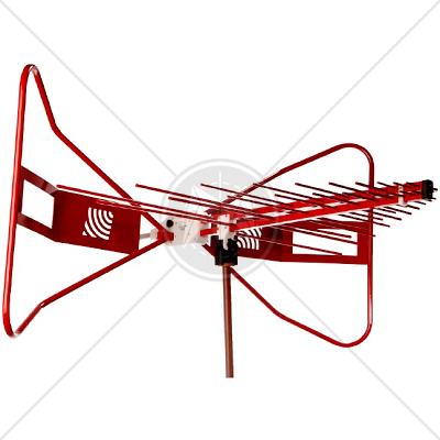
The ETS-Lindgren�s EMCO Model 3143B BiConiLog is a hybrid antenna that combines innovative design, compact size, and excellent performance. This antenna enables users to measure a frequency range of 30 MHz to 1 GHz in one sweep, negating the need for multiple antennas and time-consuming equipment setup. Accuracy and repeatability are improved, while time and money are saved.
This BiConiLog is designed as a dual-purpose antenna that can be used for both immunity and emission testing.
This model includes a stinger mount as standard equipment. Individual antenna calibration data is provided for emission testing.
Frequency Range
The Model 3143B frequency range covers from 30 MHz to 1 GHz. This frequency range covers the necessary range of emissions testing on a traditional OATS/semi-anechoic chamber setup.
VSWR Levels
Typical VSWR for the 3143B is >3:1 above 70 MHz, an excellent level at this low frequency for an antenna this size.
Emissions and Immunity Antenna
Emission measurements can be performed without having to change antennas.
For immunity measurements, the 3143B covers the typical 80 MHz to 1 GHz range.
Flexible Mounting System
The Model 3116C comes with a bracket that accepts either a 1/4� 20 thread screw or rear stinger mount.
Individually Calibrated
The 3143B is individually calibrated at 10 m per ANSI C63.5 and calibrations at 1m and 3m per SAE ARP 958.
- 30 MHz - 1 GHz Frequency Range
- >3:1 VSWR Above 70 MHz
- For Emissions and Immunity Testing
- Flexible Mounting System
- Individually Calibrated
|
Electrical Specifications
|
|
Frequency Maximum
|
1 GHz
|
|
Frequency Minimum
|
30 MHz
|
|
Pattern Type
|
Directional
|
|
Polarization
|
Linear
|
|
Physical Specifications
|
|
Width
|
133.9 cm (52.72 inches)
|
|
Depth
|
124.3 cm (48.94 inches)
|
|
Height
|
76.2 cm (30.00 inches)
|
|
Weight
|
5.5 kg ( 12.13 lb )
|
Electrical Specifications with Differing Ranges
|
Frequency Range
|
Max. Continuous Power
|
Impedance (Nominal)
|
VSWR Ratio (Avg)
|
Connectors
|
|
30 MHz - 60 MHz
60 MHz - 600 MHz
600 MHz - 1 GHz
|
500 W
1 kW
500 W
|
50 Ohm
|
3:1
|
Type N female (1)
|
Standards
|
CISPR 11 |
|
CISPR 14 - 1 |
|
CISPR 14 - 2 |
|
CISPR 14 - 2 |
|
CISPR 16 - 1 |
|
CISPR 16 - 2 |
|
CISPR 16 - 3 |
|
CISPR 16 - 4 |
|
CISPR 22 |
|
CISPR 24 |
|
IEC/TR EN 61000 - 1 - 1 |
|
IEC/TR EN 61000 - 2 - 1 |
|
IEC/TR EN 61000 - 2 - 3 |
|
IEC EN 61000 - 3 - 2 |
|
IEC EN 61000 - 3 - 4 |
|
IEC/TC EN 61000 - 3 - 5 |
|
IEC EN 61000 - 4 - 2 |
|
IEC EN 61000 - 4 - 3 |
|
IEC EN 61000 - 4 - 4 |
|
IEC EN 61000 - 4 - 5 |
|
IEC EN 61000 - 4 - 6 |
|
IEC EN 61000 - 4 - 7 |
|
IEC EN 61000 - 4 - 8 |
|
IEC EN 61000 - 4 - 9 |
|
IEC EN 61000 - 4 - 11 |
|
EN 50 081 part 1 |
|
EN 50 081 part 2 |
|
EN 55 011 |
|
EN 55 013 |
|
EN 55 014 |
|
EN 55 015 |
|
EN 55 020 |
|
EN 55 022 |
|
EN 55 024 |
|
EN 50 082 part 1 |
|
EN 50 082 part 2 |
|
EN 50 093 |
|
FCC Part 15 |
|
MIL-STD - 461E |
|