|
ELECTRICAL
|
|
|
|
|
Ranges
|
2Ω
|
20Ω
|
200Ω
|
2000Ω
|
20kΩ
|
|
Resolution
|
1mΩ
|
10mΩ
|
0.1Ω
|
1Ω
|
10Ω
|
|
Resistance Measurement Frequency
|
128Hz square wave
|
|
Test Current
|
2mA, 10mA, 50mA
|
|
Accuracy
|
±2% of Reading ± 1ct from 10% to 100% of range
|
|
Auxiliary Electrode Resistance
|
Ry: 50kΩ on 20Ω, 200Ω, 2000Ω & 20kΩ ranges; 5kΩ on 2Ω range Rz: 2mA range: 15kΩ; 10mA range: 3000Ω; 50mA range: 400Ω
|
|
Interference
|
The unit is designed to reject high levels of interference voltages at DC, or 50/60 Hz and their harmonics
|
|
Noise Influence on Accuracy
|
0.5% of range (max) to 20V peak
|
|
Power Source
|
Built-in rechargeable 12V, one Ah NiCD battery, or external 12 VDC; low battery indication.
Battery can be recharged with built-in dual voltage charging unit: 94 to 127V or 187 to 253V (47 to 450Hz)
|
|
Charging Time
|
14 hours typical
|
|
Charging Supply Voltage
|
Internally selectable 110/220V, 45 to 450Hz
|
|
Battery Life
|
Four hrs on 50mA test current (800 15 sec measurements),
Seven hrs on 2mA and 10mA test currents (1500 15 sec. measurements)
|
|
Fuse Protection
|
500Vrms measurement circuit
|
|
MECHANICAL
|
|
|
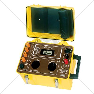
Display
|
7-segment LCD, 0.71" (18mm) high (31/2 digit); 2000-count
|
|
Connection
|
Terminals accept spade lugs with min. gap of 6mm or standard 4mm banana jacks
|
|
Operating Temperature
|
14° to 122°F (-10° to 50°C)
|
|
Dimensions
|
15.75 x 10.2 x 9.8" (400 x 260 x 250mm)
|
|
Weight
|
14 lbs (6.5kg) approximate
|
|
Case
|
Heavy-duty plastic, with detachable cover and carrying handle
|
|
Colors
|
Case: safety yellow; Front panel: brown
|
|
Dielectric Test
|
2000Vrms, 50/60Hz between 4 interconnected measuring terminals and any external metal ground; 2000Vrms, 50/60Hz between line input and measuring terminals on front panel
|
|
Environmental
|
O-ring sealed faceplate against water and dust; sealed cover when closed; IEC529, DIN 0470-T1
|
|
SAFETY
|
|
|
Rating
|
EN 61010
|
|
Double Insulation
|
Yes
|
|
Impact Resistance
|
Shock and vibration according to MIL-T-28800D class 3
|
|
CE Mark
|
Yes
|