|
Common
|
|
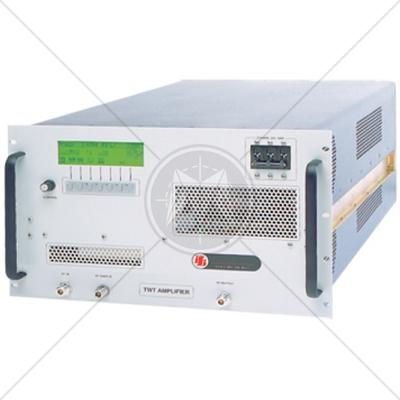
Front Panel Controls
|
Knobs with 3½ digit digital displays to control output voltage and current settings. Power on/off switch, output enable/standby switch and local/remote switch. Voltage, current and overvoltage preview push buttons allow you to preview the programmed settings at any time; overvoltage limit is adjusted with a set screw accessible through the front panel.
|
|
Displays and Indicators
|
Voltage and overvoltage setting 3½ digit LED display, current setting 3½ digit LED display. LED indicators for power on, shutdown, remote, overvoltage protection, overtemperature and front panel lockout, constant voltage and constant current modes. IEEE-488.2 indicators include error, SRQ and address (M9E option).
|
|
Built-in Protection
|
Output overvoltage (resets by cycling the enable/standby switch), overtemperature (will automatically reset)
|
|
Input
|
|
|
Voltage and Frequency 3 kW
|
180-264 VAC, 47-63 Hz, single or three phase (<200 VAC range limited to 40°C maximum)
|
|
4 kW
|
180-264 VAC, 47-63 Hz, three phase (<200 VAC range limited to 40°C maximum)
|
|
Power Factor
|
0.95 typical with three phase input, 0.98 typical with single phase input
|
|
Current
|
3 kW: single phase, 21A RMS; three phase, 12A RMS 4 kW: 180-264 VAC, 15A RMS; 345-455 VAC, 8.5A RMS; 432-528 VAC, 6.5A RMS;
|
|
Output
|
|
Regulation
|
Line: For input voltage variation over the AC input voltage range, with constant rated load. Load: For 0-100% load variation, with constant nominal line voltage. Voltage: 0.05% of maximum rated output +2mV Current: 0.1% of maximum rated output
|
|
Transient Response
|
Typically recovers in 1.5 ms to within 1% of steady-state output voltage (greater than 50% of Vmax) for 70-100% or 100-70% load change.
|
|
Stability
|
±0.05% of maximum voltage or current over 8 hours after 15 minute warm-up time at fixed line, load and temperature. Current accuracy for 5V, 8V, and 16V models is 1% typical.
|
|
Efficiency
|
5-8V Models: 82% typical 16-80V Models: 87% typical 150-600V Models: 85% typical (at maximum output power)
|
|
Temperature Coefficient
|
0.02%/°C of rated output voltage; 0.03%/°C of rated output current. Change in output per °C change in ambient temperature, with constant line and load.
|
|
Weight & Shipping Weight
|
|
Weight
|
40 lbs. (18.2 kg)
|
|
Shipping Weight
|
49 lbs. (22.3 kg)
|
|
Physical
|
|
|
Height
|
3-1/2” (88 mm)
|
|
Width
|
19” (482 mm)
|
|
Depth
|
18” (508 mm)
|
|
Environmental
|
|
Operating Temperature
|
0°C to 50°C, no derating (<200 VAC range limited to 40°C maximum)
|
|
Storage Temperature
|
-40°C to 65°C
|
|
Cooling
|
Internal fans with overtemperature protection
|
|
Output
|
|
Model
|
Preview Accuracy
|
OVP Adjustment Range (5% to 110% of Vmax)
|
|
Voltage (0.05% of Vmax +1 count)
|
Current ( 1.0% of Imax +1 count)
|
|
DLM 5-350E
|
0.04V
|
5A
|
0.3-5.5V
|
|
DLM 5-450E
|
0.04V
|
6A
|
0.3-5.5V
|
|
DLM 8-350E
|
0.05V
|
5A
|
0.4-8.8V
|
|
DLM 8-450E
|
0.05V
|
6A
|
0.4-8.8V
|
|
DLM 16-185E
|
0.09V
|
3A
|
0.8-17.6V
|
|
DLM 16-250E
|
0.09V
|
4A
|
0.8-17.6V
|
|
DLM 32-95E
|
0.3V
|
1.1A
|
1.6-35V
|
|
DLM 32-125E
|
0.3V
|
1.4A
|
1.6-35V
|
|
DLM 40-75E
|
0.3V
|
0.9A
|
2-44V
|
|
DLM 40-100E
|
0.3V
|
1.1A
|
2-44V
|
|
DLM 60-50E
|
0.4V
|
0.6A
|
3-66V
|
|
DLM 60-66E
|
0.4V
|
0.8A
|
3-66V
|
|
DLM 80-37E
|
0.5V
|
0.5A
|
4-88V
|
|
DLM 80-50E
|
0.5V
|
0.6A
|
4-88V
|
|
DLM 150-20E
|
0.9V
|
0.3A
|
7.5-165V
|
|
DLM 150-26E
|
0.9V
|
0.4A
|
7.5-165V
|
|
DLM 300-10E
|
1.6V
|
0.11A
|
15-330V
|
|
DLM 300-13E
|
1.6V
|
0.14A
|
15-330V
|
|
DLM 600-5E
|
3.1V
|
0.06A
|
30-660V
|
|
DLM 600-6.6E
|
3.1V
|
008A
|
30-660V
|
|
Output
|
|
Model
|
Ripple and Noise
|
|
Ripple (RMS)*
|
Noise (P-P)
|
|
DLM 5-350E
|
12mV
|
100mV
|
|
DLM 5-450E
|
12mV
|
100mV
|
|
DLM 8-350E
|
12mV
|
100mV
|
|
DLM 8-450E
|
12mV
|
100mV
|
|
DLM 16-185E
|
10mV
|
100mV
|
|
DLM 16-250E
|
10mV
|
100mV
|
|
DLM 32-95E
|
10mV
|
100mV
|
|
DLM 32-125E
|
10mV
|
100mV
|
|
DLM 40-75E
|
10mV
|
100mV
|
|
DLM 40-100E
|
10mV
|
100mV
|
|
DLM 60-50E
|
15mV
|
100mV
|
|
DLM 60-66E
|
15mV
|
100mV
|
|
DLM 80-37E
|
15mV
|
120mV
|
|
DLM 80-50E
|
15mV
|
120mV
|
|
DLM 150-20E
|
30mV
|
200mV
|
|
DLM 150-26E
|
30mV
|
200mV
|
|
DLM 300-10E
|
60mV
|
300mV
|
|
DLM 300-13E
|
60mV
|
300mV
|
|
DLM 600-5E
|
100mV
|
500mV
|
|
DLM 600-6.6E
|
100mV
|
500mV
|
|
* RMS ripple typical from 20 Hz to 300 kHz Specifications subject to change.
|
|
Output
|
|
Model
|
Stability
|
|
Voltage (0.05% of Vmax)
|
Current (0.05% of Imax)
|
|
DLM 5-350E
|
3 mV
|
175 mA
|
|
DLM 5-450E
|
3 mV
|
225 mA
|
|
DLM 8-350E
|
4 mV
|
175 mA
|
|
DLM 8-450E
|
4 mV
|
225 mA
|
|
DLM 16-185E
|
5 mV
|
93 mA
|
|
DLM 16-250E
|
5 mV
|
125 mA
|
|
DLM 32-95E
|
16 mV
|
48 mA
|
|
DLM 32-125E
|
16 mV
|
63 mA
|
|
DLM 40-75E
|
20 mV
|
38 mA
|
|
DLM 40-100E
|
20 mV
|
50 mA
|
|
DLM 60-50E
|
30 mV
|
25 mA
|
|
DLM 60-66E
|
30 mV
|
33 mA
|
|
DLM 80-37E
|
40 mV
|
19 mA
|
|
DLM 80-50E
|
40 mV
|
25 mA
|
|
DLM 150-20E
|
75 mV
|
10 mA
|
|
DLM 150-26E
|
75 mV
|
13 mA
|
|
DLM 300-10E
|
150 mV
|
5 mA
|
|
DLM 300-13E
|
150 mV
|
6.5 mA
|
|
DLM 600-5E
|
300 mV
|
2.5 mA
|
|
DLM 600-6.6E
|
300 mV
|
3.3 mA
|
|
Output
|
|
Model
|
Output Rating
|
|
Voltage (VDC)
|
Current (ADC)
|
|
DLM 5-350E
|
0-5
|
0-350
|
|
DLM 5-450E
|
0-5
|
0-450
|
|
DLM 8-350E
|
0-8
|
0-350
|
|
DLM 8-450E
|
0-8
|
0-450
|
|
DLM 16-185E
|
0-16
|
0-185
|
|
DLM 16-250E
|
0-16
|
0-25
|
|
DLM 32-95E
|
0-32
|
0-95
|
|
DLM 32-125E
|
0-32
|
0-125
|
|
DLM 40-75E
|
0-40
|
0-75
|
|
DLM 40-100E
|
0-40
|
0-100
|
|
DLM 60-50E
|
0-60
|
0-50
|
|
DLM 60-66E
|
0-60
|
0-66
|
|
DLM 80-37E
|
0-80
|
0-37
|
|
DLM 80-50E
|
0-80
|
0-50
|
|
DLM 150-20E
|
0-150
|
0-20
|
|
DLM 150-26E
|
0-150
|
0-26
|
|
DLM 300-10E
|
0-300
|
0-10
|
|
DLM 300-13E
|
0-300
|
0-13
|
|
DLM 600-5E
|
0-600
|
0-5
|
|
DLM 600-6.6E
|
0-600
|
0-6.6
|
|
Output
|
|
Model
|
Regulation Line and Load
|
|
Voltage (0.05% of Vmax + 2mV)
|
Current (0.1% of Imax)
|
|
DLM 5-350E
|
5 mV
|
350 mA
|
|
DLM 5-450E
|
5 mV
|
450 mA
|
|
DLM 8-350E
|
6 mV
|
350 mA
|
|
DLM 8-450E
|
6 mV
|
450 mA
|
|
DLM 16-185E
|
10 mV
|
185 mA
|
|
DLM 16-250E
|
10 mV
|
250 mA
|
|
DLM 32-95E
|
18 mV
|
95 mA
|
|
DLM 32-125E
|
18 mV
|
125 mA
|
|
DLM 40-75E
|
22 mV
|
75 mA
|
|
DLM 40-100E
|
22 mV
|
100 mA
|
|
DLM 60-50E
|
32 mV
|
50 mA
|
|
DLM 60-66E
|
32 mV
|
66 mA
|
|
DLM 80-37E
|
42 mV
|
37 mA
|
|
DLM 80-50E
|
42 mV
|
50 mA
|
|
DLM 150-20E
|
77 mV
|
20 mA
|
|
DLM 150-26E
|
77 mV
|
26 mA
|
|
DLM 300-10E
|
152 mV
|
10 mA
|
|
DLM 300-13E
|
152 mV
|
13 mA
|
|
DLM 600-5E
|
302 mV
|
55 mA
|
|
DLM 600-6.6E
|
302 mV
|
7 mA
|
|
Output
|
|
Model
|
Meter Accuracy
|
|
Voltage (0.5% of Vmax + 1 Count)
|
Current (0.75% of Imax + 1 Count)
|
|
DLM 5-350E
|
0.04 V
|
4 A
|
|
DLM 5-450E
|
0.04 V
|
5 A
|
|
DLM 8-350E
|
0.05 V
|
4 A
|
|
DLM 8-450E
|
0.05 V
|
5 A
|
|
DLM 16-185E
|
0.09 V
|
3 A
|
|
DLM 16-250E
|
0.09 V
|
3 A
|
|
DLM 32-95E
|
0.3 V
|
0.8 A
|
|
DLM 32-125E
|
0.3 V
|
1 A
|
|
DLM 40-75E
|
0.3 V
|
0.7 A
|
|
DLM 40-100E
|
0.3 V
|
0.9 A
|
|
DLM 60-50E
|
0.4 V
|
0.5 A
|
|
DLM 60-66E
|
0.4 V
|
0.6 A
|
|
DLM 80-37E
|
0.5 V
|
0.4 A
|
|
DLM 80-50E
|
0.5 V
|
0.5 A
|
|
DLM 150-20E
|
0.9 V
|
0.3 A
|
|
DLM 150-26E
|
0.9 V
|
0.3 A
|
|
DLM 300-10E
|
1.6 V
|
0.09 A
|
|
DLM 300-13E
|
1.6 V
|
0.11 A
|
|
DLM 600-5E
|
3.1 V
|
0.05 A
|
|
DLM 600-6.6E
|
3.1 V
|
0.06 A
|
|
Rear Panel Control/Monitor
|
|
Remote Sense
|
The maximum total allowed sense line drop is 2V for 5V, 8V and 16V models and 5V for all other models. Line drop subtracts from the maximum available output voltage at full rated power.
|
|
Remote Sense Protection
|
Unit will not be damaged due to misconnection of the remote sense leads.
|
|
Remote Programming
|
Voltage, current (0-100%) and OVP (5-110%) of full scale can be programmed by selectable 0-5 VDC, 0-10 VDC, or 0-5 kΩ.
|
|
Remote Monitoring
|
Voltage or current can be monitored with user-selectable ranges, 0-5 VDC or 0-10 VDC
|
|
Operational Features
|
Master/slave parallel* operation, up to 2 units can be connected in parallel with active current sharing control to within 10% of each supply. Series operation, up to 3 units of the same model type can be connected in series (consult manual). Negative terminal rated at 150 Vmax above ground
|
|
Software
|
LabVIEW® driver M9E/M85
|
|
Regulatory Compliance
|
CE Mark, 16-185 & 22-180 certified NRTL to EN 61010-1. Marked cCSAus
|