|
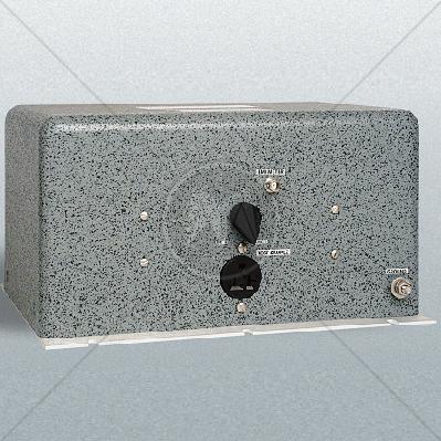
The Solar Electronics LISNs use a series inductor between the test sample and the power source to provide the impedance-versus frequency characteristic. A coaxial connector with DC isolation is provided for connection to the associated frequency selective EMI meter. The power source end of the inductor is bypassed to ground.
Due to the large current-carrying capability of some LISNs, it is not always practical to use a switch for changing inductance values. Instead, some models are equipped with a high current pin plug-and-jack combination for quickly connecting and disconnecting a network and substituting another. This nylon insulated pin plug and jack arrangement is a safety feature, well isolated from inadvertent short circuits, providing protection to operating personnel.
Current ratings up to 200 amperes are available in 50 µH styles and 500 amperes in 5 µH styles. See the chart on the following page. When measurements are made in a shielded room, the LISNs intended for F.C.C. applications will also serve for V.D.E. tests. When operating on an unfiltered power line, the V.D.E. specifications require a filter consisting of 250 µH inductor and a capacitor. This filter is included in the 24 ampere LISN, Type 9348-50-R-24-BNC, and the 50 ampere LISN, Type 8602-50-TS-50-N
Solar 8650 Application
When measuring conducted radio interference voltages from active power lines to ground, it is essential to know the line impedance so that repeatable tests can be made by more than one laboratory. Artificial line impedances are specified in MIL-STD-462, V.D.E., C.I.S.P.R., C22.4, NACSEM 5100, ANSI C63.2 and other EMI specifications.
The characteristic impedance of the 5 µH and 50 µH LISNs brackets the mean value of power line impedance which has been measured by independent researchers. These two inductance values in parallel with the 50 ohms of the EMI meter fall between the minimum and maximum line impedance values which have been measured. The mean value would be represented by a 20 µH inductor in parallel with 100 ohms.
Standards
|
CISPR 11 |
|
CISPR 14 - 1 |
|
CISPR 14 - 2 |
|
CISPR 14 - 2 |
|
CISPR 16 - 1 |
|
CISPR 16 - 2 |
|
CISPR 16 - 3 |
|
CISPR 16 - 4 |
|
CISPR 22 |
|
CISPR 24 |
|
IEC/TR EN 61000 - 1 - 1 |
|
IEC/TR EN 61000 - 2 - 1 |
|
IEC/TR EN 61000 - 2 - 3 |
|
IEC EN 61000 - 3 - 2 |
|
IEC EN 61000 - 3 - 4 |
|
IEC/TC EN 61000 - 3 - 5 |
|
IEC EN 61000 - 4 - 2 |
|
IEC EN 61000 - 4 - 3 |
|
IEC EN 61000 - 4 - 4 |
|
IEC EN 61000 - 4 - 5 |
|
IEC EN 61000 - 4 - 6 |
|
IEC EN 61000 - 4 - 7 |
|
IEC EN 61000 - 4 - 8 |
|
IEC EN 61000 - 4 - 9 |
|
IEC EN 61000 - 4 - 11 |
|
EN 50 081 part 1 |
|
EN 50 081 part 2 |
|
EN 55 011 |
|
EN 55 013 |
|
EN 55 014 |
|
EN 55 015 |
|
EN 55 020 |
|
EN 55 022 |
|
EN 55 024 |
|
EN 50 082 part 1 |
|
EN 50 082 part 2 |
|
EN 50 093 |
|
FCC Part 15 |
|
MIL-STD - 461E |
|