|
For RE01 and RE101 Magnetic Emissions Tests.
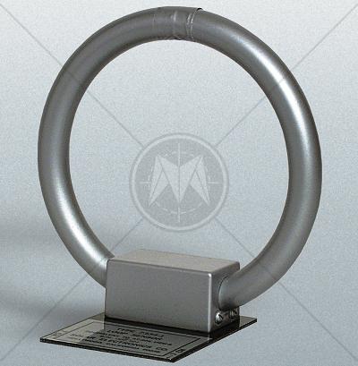
The Solar Type 7334-1 Loop Antenna has been designed as a substitute for the AT-205/URM-6 antenna and is a replacement for Eaton Model 94607-1. It uses 36 turns of wire on a 5.25" (13.3 cm) diameter form enclosed in an electrostatic shield as described in paragraph 5.2.1 of MIL-STD-461A.
The Type 7334-1 is equipped with an epoxy-glass base plate which serves as a spacer to enable the user to place the loop at exactly 7 cm from the face of the item under test as required by test procedure RE01 of MIL-STD-462.
Solar 7334-1 Application
Connection to the loop is through a BNC connector which enables coaxial cabling to the EMI receiver. The loop is supplied with a correction factor graph showing the values in dB which must be added to the reading of a 50 ohm EMI meter to obtain answers in either dB/μV/m or dB/pT. The correction factor decreases as frequency increases from 30 Hz up to approximately 15 KHz, where the factor levels off and remains relatively constant up to 5 MHz.
The Type 7334-1 Loop Antenna is required by Test Method RE01 in Parts 2 through 6 of MIL-STD-461C and RE101 of MIL-STD-461D. These portions of the specification require magnetic field emission tests of cables, equipments, systems and sub-systems installed in, or used in, all phases of military vehicles, ships, submarines, aircraft (including helicopters), spacecraft, or ground-based operations.
TEST METHODS RE01 and RE101
The Type 7334-1 Loop Antenna is positioned 7 cm from the face of the equipment under test with the plane of the loop parallel to the equipment face. The best position to begin with is opposite or near a joint or seam.
The associated EMI meter is then scanned over the range 30 Hz to 100 KHz searching for emissions. At the frequencies where emissions are found, the loop antenna is moved about the surface seeking the strongest emission level. When a strong signal is detected, the loop is oriented on its axis for a maximum reading.
This procedure is repeated for all surfaces of the equipment under test. Although the specification is not clear on the point, it appears to indicate that all six sides (including the bottom) of an equipment must be tested in this manner.
When testing cables, the loop antenna is placed 7 cm from the cable with the plane of the loop parallel to the cable. The non metallic base plate of the Type 7334-1 Loop Antenna provides a convenient means for establishing the correct 7 cm distance.
Standards
|
CISPR 11 |
|
CISPR 14 - 1 |
|
CISPR 14 - 2 |
|
CISPR 14 - 2 |
|
CISPR 16 - 1 |
|
CISPR 16 - 2 |
|
CISPR 16 - 3 |
|
CISPR 16 - 4 |
|
CISPR 22 |
|
CISPR 24 |
|
IEC/TR EN 61000 - 1 - 1 |
|
IEC/TR EN 61000 - 2 - 1 |
|
IEC/TR EN 61000 - 2 - 3 |
|
IEC EN 61000 - 3 - 2 |
|
IEC EN 61000 - 3 - 4 |
|
IEC/TC EN 61000 - 3 - 5 |
|
IEC EN 61000 - 4 - 2 |
|
IEC EN 61000 - 4 - 3 |
|
IEC EN 61000 - 4 - 4 |
|
IEC EN 61000 - 4 - 5 |
|
IEC EN 61000 - 4 - 6 |
|
IEC EN 61000 - 4 - 7 |
|
IEC EN 61000 - 4 - 8 |
|
IEC EN 61000 - 4 - 9 |
|
IEC EN 61000 - 4 - 11 |
|
EN 50 081 part 1 |
|
EN 50 081 part 2 |
|
EN 55 011 |
|
EN 55 013 |
|
EN 55 014 |
|
EN 55 015 |
|
EN 55 020 |
|
EN 55 022 |
|
EN 55 024 |
|
EN 50 082 part 1 |
|
EN 50 082 part 2 |
|
EN 50 093 |
|
FCC Part 15 |
|
MIL-STD - 461E |
|