»  Categories   »      Voltage Surge Generator   »    Surge Generator   »    Pulse Generator   »    EFT/Burst Generator   »    Generator   »    Telecommunication   »    EMC / EMI  

image enlarge

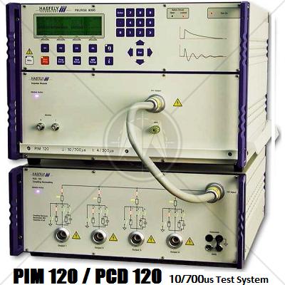
Haefely PIM 120 & PCD 120 10/700us Test System

Description

To test telecom systems the 10/700us impulse also called telecom impulse is used. This impulse is characterized by high energy and a relative fast rise time.

The 10/700us test system includes with the impulse module PIM 120 and the automatic coupling network PCD 120. It is used to generate and superimpose 10/700us impulses onto telecom and other communication lines.

The PCD 120 as part of the PSURGE 8000 system is tailored to meet the ITU and IEC requirements for 2 & 4 wire interfaces. It allows the selection of both the required resistors and coupling elements and to perform a fully automatic test sequence.

Safety is paramount with surge impulses. The PIM 120 High Voltage connections are all linked into the System Safety Concept which prevents high voltage plugs or cables from exposing operators to potentially lethal voltages. The PCD 120 has special HV output sockets to guarantee maximum safety for the user.

PSURGE 8000 Surge Platform provides all the programming functions required to perform IEC, ITU and testing without the need of a control computer. Voltage and Current peak measurement circuits are used to help determine EUT PASS/FAIL criteria. The integration in the WinFEAT&R control and reporting software package enhances an efficient set-up and operation of this test system. Most importantly, the test load can be transferred to a computer freeing valuable resources.

Features

  • 10/700us impulse shape up to 7.4kV
  • According to ITU K.44
  • Fully automatic coupling network
  • Current limit resistors 25 Ohm, 50 Ohm, 75 Ohm and 100 Ohm
  • Coupling elements user changeable, gas arrestor 90V are standard
  • Selected resistors and coupling elements clearly shown on the PCD 120 front panel
  • WinFEAT&R software integrated

Applications

  • Resistibility tests
  • ITU K.20, K.21 & K.45 Telecom Interfaces
  • EMC tests
  • IEC 61000-4-5 Data lines
  • Safety tests

Specifications

PIM 120

Impulse Voltage

0.20 – 7.4kV ±10%

Source Impedance

15 & 40 Ohms

Repetition @ Umax

10 seconds / 6 per minute

Impulse front time

V= 10us ±30% & I= 5us ±20%

Impulse duration

V= 700us ±20% & I= 320us ±20%

Impulse Polarity

Positive and Negative

PCD 120

Impulse Shape

10/700us

Current limiting resistors

4 x 25 Ohm

4 x 50 Ohm

4 x 75 Ohm

4 x 100 Ohm

Impulse output

safety HV sockets 4mm

Max. amplitude

7.4kV

Coupling elements

- gas arrestors 90V

- gas arrestor // 100nF

- direct

Max. voltage on EUT lines

dependant on used coupling element

Dimensions (W x H x D)

PIM 120

45 x 20 x 57 cm

PCD120

45 x 20 x 57 cm

Weights

PIM 120

29 kg

PCD120

22 kg

Standards

CISPR
CISPR 11
CISPR 14 - 1
CISPR 14 - 2
CISPR 14 - 2
CISPR 16 - 1
CISPR 16 - 2
CISPR 16 - 3
CISPR 16 - 4
CISPR 22
CISPR 24
IEC
IEC/TR EN 61000 - 1 - 1
IEC/TR EN 61000 - 2 - 1
IEC/TR EN 61000 - 2 - 3
IEC EN 61000 - 3 - 2
IEC EN 61000 - 3 - 4
IEC/TC EN 61000 - 3 - 5
IEC EN 61000 - 4 - 2
IEC EN 61000 - 4 - 3
IEC EN 61000 - 4 - 4
IEC EN 61000 - 4 - 5
IEC EN 61000 - 4 - 6
IEC EN 61000 - 4 - 7
IEC EN 61000 - 4 - 8
IEC EN 61000 - 4 - 9
IEC EN 61000 - 4 - 11
European
EN 50 081 part 1
EN 50 081 part 2
EN 55 011
EN 55 013
EN 55 014
EN 55 015
EN 55 020
EN 55 022
EN 55 024
EN 50 082 part 1
EN 50 082 part 2
EN 50 093
American
FCC Part 15
MIL-STD - 461E