»  Categories   »      Data Acquisition  

image enlarge

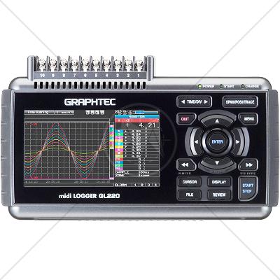
Graphtec GL 220 Data Acquisition / Data Logger 10 Channel

Description

The GL220 accepts voltage, temperature, humidity, pulse and logic signals. Channel-to-channel isolation means wiring errors or overloaded channels do not affect neighboring channels. Sensors are connected via rear mounted screw terminals. The built-in 2GB memory is non-volatile so that data is retained even if the power supply is interrupted.

Connect a USB memory stick to the USB for additional data storage. With a 512M device, users can capture data for up to 269 days (10 channels, 1 second sampling rate). Connect a PC through the USB Type B port for direct data capture to PC, data transfer and control.

An optional battery pack is available for portable use. The battery pack allows up to 6 hours of operation.

The GL220 is supplied with PC application software. The software allows for real-time waveform monitoring as well as data upload and data export to spreadsheets such as Excel.

Hot-Swap linked function can be performed when capturing to the external USB memory drive.

Capturing directly to the PC can now be performed at a speed of up to 100ms (sampling rate).

Features

  • Configuration and channel setup via USB or Ethernet
  • Real time data storage to hard disk
  • Stored data import from GL220
  • Email notification of errors and alarms
  • Available measurement modes: Y-T and X-Y
  • Separate screens are available for each of the settings
  • Direct Excel transfer can be enabled as a report function
  • Accepts Voltage (20mv to 50V), Thermo-couplers (K,E,J,T,N,R,S,T,B,W) Humidity input (when optional sensor B-530 is used)
  • 16-bit ADC resolution
  • 4.3" TFT color LCD display (WQVGA: 480 x 272 pixels)
  • Waveform and text display modes
  • Easy-to-use keypad menu system
  • Single open-collector alarm output
  • Range of trigger functions
  • Real-time statistical calculation
  • Ring Capture Function
  • Built-in 2GB memory
  • 2 x USB 2.0 interfaces - one for USB Memory stick and one for PC connection
  • Built-in battery for 6 hour operation
  • Scan speed - 0.1s/sec for all 10 channels maximum
  • Includes also 1 pulse input, 1 trigger input
  • Ultra small (7.63in x 4.63in x 1.65in)
  • Supplied with mains PSU
  • Includes Windows software for setup, control, data transfer, data conversion to ASCII and Excel formats, and on-screen data review with cursors

Specifications

Item

Description

Number of analog input channels

10 channels

External input/output

Input *

Trigger or Sampling input 1 ch, Logic or Pulse input 4 channels

Output *

Alarm output 4 channels

Sampling interval

10 ms to 1 h (in 10ms to 50ms, voltage only and limited channel), External

Time scale

1 sec to 24 hour /division

Trigger function

Action

Start or stop capturing data by the trigger

Source

Start: Off, Input signal, Alarm, External * , Clock, Week or Time

Stop: Off, Input signal, Alarm, External * , Clock, Week or Time

Combination

OR or AND condition at the level of signal or edge of signal

Condition

 Analog: Rising, Falling, Window-in, Window-out

Pulse: Rising, Falling, Window-in, Window-out

Logic: Rising or Falling

Alarm function

Detecting method

Level or edge of signal

Condition

Analog: Rising, Falling, Window-in, Window-out

Pulse: Rising, Falling, Window-in, Window-out

Logic: Rising, Falling

Alarm output *

4 channels, Output type: Open collector (pull-up resistor 10 kΩ)

Pulse input function *

Accumulating count mode

Accumulating the number of pulses from the start of measurement

Range: 50, 500, 5 k, 50 k, 500 k, 5 M, 50 M, 500 M counts/F.S.

Instant count mode

Counting the number of pulses per sampling interval

Range: 50, 500, 5 k, 50 k, 500 k, 5 M, 50 M, 500 M counts/F.S.

Rotation count (RPM) mode

Counting the number of pulses per sec. and then it is converted to RPM

Range: 50 rpm, 500 rpm, 5 krpm, 50 krpm, 500 krpm, 5 Mrpm, 50 Mrpm, 500 Mrpm /F.S.

Max. input pulse rate

50 k pulses/sec or 50k counts per sampling interval, 16 bits counter is used

Calculation function

Between Channels

Addition, Subtraction, Multiplication and Division for analog input

Statistical

Select two calculations from Average, Peak, Max., Min., RMS

Search function

Search for analog signal levels, values of logic or pulse or alarm point in captured data

Interface to PC

USB (Full speed)

Storage device

Built-in Flash memory (2 giga-bytes), USB memory device *

Data saving function

Captured Data

Direct saving of data into built-in Flash memory or USB memory device

Others

Setting conditions, Screen copy

Ring capturing mode

Function: ON/OFF, Number of capturing point: 1,000 to 2,000,000

(Size of the capture data will be limited to 1/3 of available memory)

USB memory device emulation

USB Memory emulation mode (Transfer or delete the file in built-in memory)

Engineering scale function

Set based on the reference point of the scaled output and input signal for each channel (Voltage measurement: four points are necessary to scale the output, Temperature measurement: two points are necessary to scale the output).

Display

Size

4.3 inch TFT color LCD (WQVGA: 480 x 272 dots)

Formats

Waveform + Digital, Waveform only, Calculation + Digital, Expanded digital

Operating environment

0 to 45 °C, 5 to 85 %RH

(When operating with battery pack 0 to 40 °C, charging battery 15 to 35 °C)

Power source

AC adapter (100 to 240 V, 50/60 Hz), DC power (8.5 to 24 V DC, max. 26.4 V) * , Battery pack *

Power consumption

29 VA or lower (when operating with AC adapter, displaying LCD)

External dimensions (W×D×H)

approx. 7.63in x 4.63in x 1.65in

Weight

approx. 520 g (Excluding AC adapter and battery pack)

Standards

CISPR
CISPR 11
CISPR 14 - 1
CISPR 14 - 2
CISPR 14 - 2
CISPR 16 - 1
CISPR 16 - 2
CISPR 16 - 3
CISPR 16 - 4
CISPR 22
CISPR 24
IEC
IEC/TR EN 61000 - 1 - 1
IEC/TR EN 61000 - 2 - 1
IEC/TR EN 61000 - 2 - 3
IEC EN 61000 - 3 - 2
IEC EN 61000 - 3 - 4
IEC/TC EN 61000 - 3 - 5
IEC EN 61000 - 4 - 2
IEC EN 61000 - 4 - 3
IEC EN 61000 - 4 - 4
IEC EN 61000 - 4 - 5
IEC EN 61000 - 4 - 6
IEC EN 61000 - 4 - 7
IEC EN 61000 - 4 - 8
IEC EN 61000 - 4 - 9
IEC EN 61000 - 4 - 11
European
EN 50 081 part 1
EN 50 081 part 2
EN 55 011
EN 55 013
EN 55 014
EN 55 015
EN 55 020
EN 55 022
EN 55 024
EN 50 082 part 1
EN 50 082 part 2
EN 50 093
American
FCC Part 15
MIL-STD - 461E