»  Categories   »      Power Meter   »    Meter   »    Power Quality Analyzer   »    Analyzer  

image enlarge

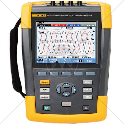
Fluke 435 Series II Power Quality and Energy Analyzer

Description

Think of the Fluke 435 II Power Quality and Energy Analyzer as your insurance policy. No matter what goes wrong in your facility, with the 435 II you will always be prepared. Equipped with advanced power quality functions and energy monetization capabilities, there is no electrical issue this model can't handle.

Features

  • Power inverter efficiency:
    • Simultaneously measure AC output power and DC input power for power electronics systems using optional DC clamp.
  • PowerWave data capture:
    • Capture fast RMS data, show half-cycle and waveforms to characterize electrical system dynamics (generator start-ups, UPS switching etc.).
  • Energy loss calculator:
    • Classic active and reactive power measurements, unbalance and harmonic power, are quantified to pinpoint the fiscal costs of energy losses.
  • Troubleshoot real-time:
    • Analyze the trends using the cursors and zoom tools.
  • Highest safety rating in the industry:
    • 600 V CAT IV/1000 V CAT III rated for use at the service entrance.
  • Measure all three phases and neutral:
    • With included four flexible current probes with enhanced thin flex design to fit into the tightest places.
  • Automatic Trending:
    • Every measurement is always automatically recorded, without any set-up.
  • System-Monitor:
    • Ten power quality parameters on one screen according to EN50160 power quality standard.
  • Logger function:
    • Configure for any test condition with memory for up to 600 parameters at user defined intervals.
  • View graphs and generate reports:
    • With included analysis software.
  • Battery life:
    • Seven hours operating time per charge on Li-ion battery pack.

Fluke 435 II Applications

  • PowerWave data capture –
    • capture fast RMS values to see every waveform so you can determine how the voltage, current and frequency values are interacting
  • Power inverter efficiency –
    • Power inverter efficiency
  • Energy monetization –
    • calculate the fiscal cost of energy waste due to poor power quality
  • Energy assessment –
    • quantify the before and after installation improvements in energy consumption to justify energy saving devices
  • Frontline troubleshooting –
    • quickly diagnose problems on-screen to get your operation back online
  • Predictive maintenance –
    • detect and prevent power quality issues before they cause downtime
  • Long-term analysis –
    • uncover hard-to-find or intermittent issues
  • Load studies –
    • verify electrical system capacity before adding loads

Specifications

Volt

Vrms (ac+dc)

435-II

1 V to 1000 V phase to neutral

0.01 V

± 0.1% of nominal voltage**** 

Vpk


1 Vpk to 1400 Vpk

1 V

5% of nominal voltage

Voltage Crest Factor (CF)


1.0 > 2.8

0.01

± 5 %

Vrms½

435-II


0.1 V

± 0.2% of nominal voltage

Vfund

435-II


0.1 V

± 0.1% of nominal voltage

Amps (accuracy excluding clamp accuracy)

Amps (ac +dc)

i430-Flex 1x 

5 A to 6000 A

1 A

± 0.5% ± 5 counts

i430-Flex 10x

0.5 A to 600 A

0.1 A

± 0.5% ± 5 counts

1mV/A 1x

5 A to 2000 A

1A

± 0.5% ± 5 counts

1mV/A 10x

0.5 A A to 200 A (ac only)

0.1 A

± 0.5% ± 5 counts

Apk

i430-Flex 

8400 Apk 

1 Arms

± 5 %

1mV/A

5500 Apk

1 Arms

± 5 %

A Crest Factor (CF)


1 to 10

0.01

± 5 %

Amps½

i430-Flex 1x 

5 A to 6000 A 

1 A 

± 1% ± 10 counts 

i430-Flex 10x

0.5 A to 600 A

0.1 A 

± 1% ± 10 counts

1mV/A 1x  

5 A to 2000 A 

1A 

± 1% ± 10 counts

1mV/A 10x

0.5 A A to 200 A (ac only)

0.1 A

± 1% ± 10 counts

Afund

i430-Flex 1x 

5 A to 6000 A

1 A

± 0.5% ± 5 counts 

i430-Flex 10x 

0.5 A to 600 A

0.1 A

± 0.5% ± 5 counts

1mV/A 1x 

5 A to 2000 A

1A

± 0.5% ± 5 counts

1mV/A 10x 

0.5 A A to 200 A (ac only)

0.1 A

± 0.5% ± 5 counts

Hz

Hz

Fluke 435 @ 50 Hz nominal

42.500 Hz to 57.500 Hz


0.001 Hz


± 0.01 Hz

Fluke 435 @ 60 Hz nominal 

51.000 Hz to 69.000 Hz


0.001 Hz


± 0.01 Hz

Power

Watts (VA, var)

i430-Flex 

max 6000 MW

0.1 W to 1 MW

± 1% ± 10 counts

1 mV/A

max 2000 MW

0.1 W to 1 MW

± 1% ± 10 counts

Power factor (Cos j/DPF)


0 to 1

0.001

± 0.1% @ nominal load conditions

Energy

kWh (kVAh, kvarh)

i430-Flex 10x

Depends on clamp scaling and V nominal

± 1% ± 10 counts

Energy loss

i430-Flex 10x

Depends on clamp scaling and V nominal

± 1% ± 10 counts Excluding line resistance accuracy

Harmonics

Harmonic order (n)


DC, 1 to 50 Grouping: Harmonic groups according to IEC 61000-4-7

Inter-harmonic order (n)


OFF, 1 to 50 Grouping: Harmonic and Interharmonic subgroups according to IEC 61000-4-7

Volts

%f

0.0 % to 100 %

0.1 %

± 0.1% ± n x 0.1 %

%r

0.0 % to 100 %

0.1 %

± 0.1% ± n x 0.4 %

Absolute

0.0 to 1000 V

0.1 V

± 5% *

THD

0.0 % to 100 %

0.1 %

± 2.5 %

Amps

%f

0.0 % to 100 %

0.1 %

± 0.1% ± n x 0.1%

%r

0.0 % to 100 %

0.1 %

± 0.1% ± n x 0.4 %

Absolute

0.0 to 600 A

0.1 A

± 5% ± 5 counts

THD

0.0 % to 100 %

0.1 %

± 2.5 %

Watts

%f or %r 

0.0 % to 100 %

0.1 %

± n x 2%

Absolute

Depends on clamp scaling and V nominal 

± 5% ± n x 2 % ± 10 counts

THD

0.0 % to 100 %  

0.1 %

± 5 %

Phase Angle


-360° to +0°

± n x 1°

Flicker

Plt, Pst, Pst(1min) Pinst


0.00 to 20.00

0.01

± 5 %

Unbalance

Volts

%

0.0 % to 20.0 %

0.1 %

± 0.1 %

Amps

%

0.0 % to 20.0 %

0.1%

± 1 %

Mains signaling

Threshold levels


Threshold, limits and signaling duration is programmable for two signaling frequencies

Signaling frequency


60 Hz to 3000 Hz

0.1 Hz


Relative V%


0 % to 100 %

0.10 %

± 0.4 %

Absolute V3s (3 second avg.)


0.0 V to 1000 V

0.1 V

± 5 % of nominal voltage

General specifications

Case

Design Rugged, shock proof with integrated protective holster Drip and dust proof IP51 according to IEC60529 when used in tilt stand position Shock and vibration Shock 30 g, vibration: 3 g sinusoid, random 0.03 g 2 /Hz according to MIL-PRF-28800F Class 2

Display

Brightness: 200 cd/m 2 typ. using power adapter, 90 cd/m 2 typical using battery power Size: 127 mm x 88 mm (153 mm/6.0 in diagonal) LCD Resolution: 320 x 240 pixels Contrast and brightness: user-adjustable, temperature compensated

Memory

8GB SD card (SDHC compliant, FAT32 formatted) standard, upto 32GB optionally Screen save and multiple data memories for storing data including recordings (dependent on memory size)

Real-time clock

Time and date stamp for Trend mode, Transient display, System Monitor and event capture

Environmental

Operating temperature

0 °C ~ +40 °C; +40 °C ~ +50 °C excl. battery

Storage temperature

-20 °C ~ +60 °C

Humidity

+10 °C ~ +30 °C: 95% RH non-condensing
+30 °C ~ +40 °C: 75% RH non-condensing
+40 °C ~ +50 °C: 45% RH non-condensing

Maximum operating altitude

Up to 2,000 m (6666 ft) for CAT IV 600 V, CAT III 1000 V
Up to 3,000 m (10,000 ft) for CAT III 600 V, CAT II 1000 V
Maximum storage altitude 12 km (40,000 ft)

Electro-Magnetic-Compatibility (EMC)

EN 61326 (2005-12) for emission and immunity

Interfaces

mini-USB-B, Isolated USB port for PC connectivity SD card slot accessible behind instrument battery

Standards

CISPR
CISPR 11
CISPR 14 - 1
CISPR 14 - 2
CISPR 14 - 2
CISPR 16 - 1
CISPR 16 - 2
CISPR 16 - 3
CISPR 16 - 4
CISPR 22
CISPR 24
IEC
IEC/TR EN 61000 - 1 - 1
IEC/TR EN 61000 - 2 - 1
IEC/TR EN 61000 - 2 - 3
IEC EN 61000 - 3 - 2
IEC EN 61000 - 3 - 4
IEC/TC EN 61000 - 3 - 5
IEC EN 61000 - 4 - 2
IEC EN 61000 - 4 - 3
IEC EN 61000 - 4 - 4
IEC EN 61000 - 4 - 5
IEC EN 61000 - 4 - 6
IEC EN 61000 - 4 - 7
IEC EN 61000 - 4 - 8
IEC EN 61000 - 4 - 9
IEC EN 61000 - 4 - 11
European
EN 50 081 part 1
EN 50 081 part 2
EN 55 011
EN 55 013
EN 55 014
EN 55 015
EN 55 020
EN 55 022
EN 55 024
EN 50 082 part 1
EN 50 082 part 2
EN 50 093
American
FCC Part 15
MIL-STD - 461E