»  Categories   »      Log Periodic Antenna   »    Dipole Antenna   »    Antenna  

image enlarge

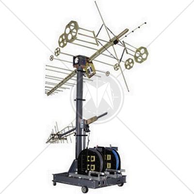
ETS-Lindgren 3151 Log Periodic Dipole Array Antenna 20 MHz – 220 MHz

Description

The Model 3151 Foreshortened Log Periodic Dipole Antenna features a convenient space-saving design with the use of top hat-loaded, low-frequency elements. This reduced-sized design has optimized impedance loading to simulate the moderate gain of a full-size LPDA. Without size reduction, the longest dipole element length would be approximately 7.5 m (24.6 ft). Instead, the Model3151’s entire width is only 3.5 m (11.5 ft).To enhance measurement repeatability, the Model 3151’s longest elements are supported with nylon straps to ensure consistent element positioning.

The 3151 antenna features a specially-designed feed to handle high power requirements of up to 5 kW for generating high electric field strength. A hairpin matching stub is used to improve the low-frequency VSWR, which minimizes mismatch loss between the amplifier and antenna.

The 3151 antenna is constructed of lightweight, corrosion-resistant aluminum, providing years of trouble-free service. All elements are attached with knurled knobs for easy assembly.

The included wheeled pedestal permits horizontal and vertical antenna polarization, and tilt-angle adjustments. A pneumatic cylinder is used to change polarization, and can be remotely controlled using an optional ETS-EMCO Model 2090 Controller or an ETS-EMCO 2190 Virtual Controller. The Model 2090 is IEEE-488 compatible, and uses fiber optic I/O for communication with the pedestal.

Electric Field distribution
The Model 3151 is used for both horizontal and vertical polarizations. The phase center /source position of the antenna shifts from the rear to the front end of the boom as frequency increases. To ensure a high field strength at the low frequency range(30 MHz - 45 MHz), the LPDA antenna needs to be placed at a close distance. However, the beam width of the antenna gets narrower at higher frequencies. Therefore, the antenna needs to be placed at a farther distance at higher frequencies to cover a larger uniform area. If the same distance is kept for the high and low frequency ranges, the field uniformity is compromised above 80 MHz.

Features

  • 20 MHz to 220 MHz frequency range
  • High power feed handles up to 5 kW RF input power
  • Space saving design features tophat-loaded, low-frequency elements
  • Mounted on wheeled base for easy mobility

Specifications

Electrical Specifications

Frequency Minimum

20 MHz 

Frequency Maximum

220 MHz 

Input Impedance

50 Ω

Pattern Type

Directional 

Polarization

Linear 

SWR Ratio (AVG)

1.5:1 average, 6:1 maximum

Maximum RF Input Power

5 kW

Physical Specifications

Length

5.3 m (13.4 ft.)

Width

5.3 m (13.4 ft.)

Height

4.6 m (11.7 ft.) 

Standards

CISPR
CISPR 11
CISPR 14 - 1
CISPR 14 - 2
CISPR 14 - 2
CISPR 16 - 1
CISPR 16 - 2
CISPR 16 - 3
CISPR 16 - 4
CISPR 22
CISPR 24
IEC
IEC/TR EN 61000 - 1 - 1
IEC/TR EN 61000 - 2 - 1
IEC/TR EN 61000 - 2 - 3
IEC EN 61000 - 3 - 2
IEC EN 61000 - 3 - 4
IEC/TC EN 61000 - 3 - 5
IEC EN 61000 - 4 - 2
IEC EN 61000 - 4 - 3
IEC EN 61000 - 4 - 4
IEC EN 61000 - 4 - 5
IEC EN 61000 - 4 - 6
IEC EN 61000 - 4 - 7
IEC EN 61000 - 4 - 8
IEC EN 61000 - 4 - 9
IEC EN 61000 - 4 - 11
European
EN 50 081 part 1
EN 50 081 part 2
EN 55 011
EN 55 013
EN 55 014
EN 55 015
EN 55 020
EN 55 022
EN 55 024
EN 50 082 part 1
EN 50 082 part 2
EN 50 093
American
FCC Part 15
MIL-STD - 461E