»  Categories   »      Combo Wave Generator   »    Generator   »    Surge Generator  

image enlarge

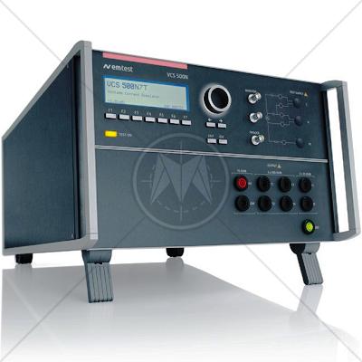
EM TEST VCS 500N10T Combo Wave & Telecom Surge Generator 10kV

Description

Surge pulses occur due to direct or indirect lightning strokes to an external (outdoor) circuit. This leads to currents or electromagnetic fields causing high voltage or current transients. Another source for surge pulses is switching transients originating from switching disturbances and systems faults.

Due to the characteristic of the phenomenon nearly every electrical and electronically a device may suffer from such lightning events which justifies the necessity of surge tests being widely performed. Surge voltage can reach several thousands of volts and surge current is seen to reach several thousands of amps.

The VCS 500N10T unifies the test capabilities for Combination wave surge and telecom surge testing in one unit up to 10kV. Moreover it offers built-in coupling resistors for telecom port testing.

For combination wave surge tests on high-current mains supply lines its capability can be extended by an external CDN to achieve nominal currents of 100A and more per phase.
By selecting the desired coupling the source impedance and the coupling capacitor is set automatically whatever CDN is connected.

Fail inputs are offered as standard for DUT monitoring purposes. Peak values of voltage and current are shown in the display and these values are transferred to the software for reporting.

To comply with safety regulations the VCS 500N10T is equipped with a contact to control warning lamps and with a safety interlock.

Pre-programmed Standard Test routines allow highest user convenience. Still the VCS 500N10T offers the Quick Start test routine where parameters can be changed on-line during the test to evaluate the susceptibility level of an individual DUT.

Features

  • Combination Wave up to 10kV/5kA
  • Telecom surge voltage up to 10kV
  • Telecom surge current up to 666A
  • Repetition rate 60s @10kV Surge
  • Built-in coupling for telecom port testing
  • Voltage/current monitors
  • Interlock
  • Warning lamp control
  • Manual operation
  • USB and GPIB interface

Specifications

AC POWER PORT TESTING, PULSE 1.2/50US - 8/20US AS PER IEC 61000-4-5

Voltage (o.c.)

500V - 10,000V ±10%

Rise time

1.2us ± 30%

Pulse duration

50us ± 20%

Current (s.c.)

250A - 5,000A

Rise time

8us ± 20%

Pulse duration

20us ± 20%

Polarity

Positive, negative or alternating

Counter

1 - 30,000 or endless

TELECOM PORT TESTING, PULSE 10/700US - 4/300US AS PER IEC 61000-4-5

Voltage (o.c.)

500V - 10,000V ±10%

Rise time

10us ± 30%

Pulse duration

700us ± 20%

Current (s.c.)

12.5A - 250A

Rise time

4us ± 20%

Pulse duration

300us ± 20%

Energy storage capacitor

20uF

Source impedance

40ohm (15ohm from generator and 25ohm at Tx)

Polarity

Positive, negative or alternating

Counter

1 - 30,000 or endless

TELECOM TESTING PULSE 10/700US AS PER ITU AND ETS RECOMMENDATIONS

Voltage (o.c.)

500V - 10,000V ±10%

Rise time

10us ± 30%

Pulse duration

700us ± 20%

Energy storage capacitor

20uF

Polarity

Positive, negative or alternating

Counter

1 - 30,000 or endless

INTERFACE

Serial interface

USB

Parallel interface

IEEE 488, addresses 1 - 30

CN interface

To control external coupling matrix

DIMENSIONS

Dimensions

19"/12HU

Weight

approx. 44kg

Standards

CISPR
CISPR 11
CISPR 14 - 1
CISPR 14 - 2
CISPR 14 - 2
CISPR 16 - 1
CISPR 16 - 2
CISPR 16 - 3
CISPR 16 - 4
CISPR 22
CISPR 24
IEC
IEC/TR EN 61000 - 1 - 1
IEC/TR EN 61000 - 2 - 1
IEC/TR EN 61000 - 2 - 3
IEC EN 61000 - 3 - 2
IEC EN 61000 - 3 - 4
IEC/TC EN 61000 - 3 - 5
IEC EN 61000 - 4 - 2
IEC EN 61000 - 4 - 3
IEC EN 61000 - 4 - 4
IEC EN 61000 - 4 - 5
IEC EN 61000 - 4 - 6
IEC EN 61000 - 4 - 7
IEC EN 61000 - 4 - 8
IEC EN 61000 - 4 - 9
IEC EN 61000 - 4 - 11
European
EN 50 081 part 1
EN 50 081 part 2
EN 55 011
EN 55 013
EN 55 014
EN 55 015
EN 55 020
EN 55 022
EN 55 024
EN 50 082 part 1
EN 50 082 part 2
EN 50 093
American
FCC Part 15
MIL-STD - 461E