»  Categories   »      Signal Generator   »    Generator  

image enlarge

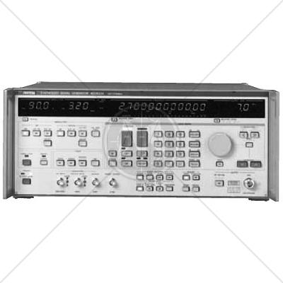
Anritsu MG3633A Synthesized Signal Generator 10 kHz - 2.7 GHz

Description

The MG3633A has excellent frequency resolution, frequency switching speed, signal purity, and a high output level in addition to amplitude, frequency, and phase modulation functions.

Also, sweep functions are provided for carrier frequency, output level, and modulation frequency so an appropriate sweep can be performed for various devices to be measured. Also, the MG3633A has a frequency memory that can store 1000 carrier frequencies and a function memory that stores 100 panel settings. Moreover, since the maximum output level is +17 dBm, it can be used for various local signal sources.

The MG3633A is suitable for research and development of mobile communications in the quasi-microwave band, performance evaluation, characteristics testing, and adjustment of various types of radio equipment such as digital land-based mobile communications, mobile satellite communications, satellite broadcasting, and radio LANs.

Features

Low Noise
Using both the latest synthesizer and RF-device technologies and optical data links in the internal control circuit, the SSB phase noise has been cut to -140 dBc/Hz (CW, 1.1 GHz, offset 20 kHz). In particular, the MG3633A shows its power in measurement of narrow-band radio equipment S/N ratio and adjacent channel selectivity.

High accuracy and high-output level
Low levels of -123 dBm can be set with ±1 dB accuracy by using a high-accuracy programmable attenuator. The output level can be displayed in units of dBm, dBµV, V, mV, and µV or as a relative value (dB).

Modulation characteristics
The MG3633A has AM, FM, oM, and a combination of all three modulation functions. A DC mode is provided for FM, which makes simulation of digital transmissions for a pager possible. Also, a built-in AF oscillator with a 0.1 Hz to 100 kHz synthesizer can handle various modulations.

Quasi-microwave output
The MG3633A covers a wide range (from 10 kHz to 2700 MHz) and is suitable for research and development, as well as production of quasi-microwave band radio equipment.

Specifications


Carrier frequency

Range

10 kHz to 2700 MHz

Resolution

0.01 Hz

Accuracy

Same as that of the reference oscillator


Internal reference oscillator*1

Frequency: 10 MHz

Start-up characteristics: After 30 minutes of operation: ≤1 x 10⁻⁷/day, after 60 minutes of operation: ≤5 x 10⁻⁸/day, Aging rate: After 24 hours of operation: ≤2 x 10⁻⁸/day,

Temperature characteristics: ±5 x 10⁻⁸/day, (0˚ to 50˚C)

External reference signal input


10 MHz, TTL Level, BNC connector on rear panel

Reference signal output

10 MHz, TTL Level, BNC connector on rear panel


Switching time

≤10 ms (time from last command until frequency has stabilized to within ±500 Hz of set frequency, during remote operation)


Output

Range

–143 to +23 dBm

Units

dBm, dBµV, V, mV, µV (Terminated and open voltages are selectable for dBµV, V, mV or µV.)

Resolution

0.1 dB

Frequency response

±0.5 dB referred to 0 dBm (<1280 MHz), ±1 dB referred to 0 dBm (≥1280 MHz)


Accuracy

Frequency Output level


10 kHz to <1280 MHz


≥1280 MHz

+17.1 to +23 dBm

+15.1 to +17 dBm

±1 dB

–122.9 to +15 dBm

±1 dB

±2 dB

–132.9 to –123 dBm

±3 dB

±4 dB

–143 to –133 dBm

Impedance

50 Ω, N-type connector

VSWR: ≤1.5 (<1280 MHz, ≤–3 dBm), ≤1.8 (≥1280 MHz, ≤–3 dBm)


Switching time

Time from last command until output level is stabilized, during remote operation:≤25 ms (at LEVEL NORMAL mode)

≤80 ms (when setting level is crossing over –59 dBm, at LEVEL NORMAL mode)

≤5 ms (at LEVEL CONTINUOUS mode)

Interference radiation

≤1 µV (Value is voltage terminated with 50 Ω load, measured 25 mm from front panel with a two-turn 25 mm diameter loop antenna.) Except sweep mode

Range

10 kHz to 2700 MHz

Resolution

0.01 Hz

Accuracy

Same as that of the reference oscillator


Internal reference oscillator*1

Frequency: 10 MHz

Start-up characteristics: After 30 minutes of operation: ≤1 x 10⁻⁷/day, after 60 minutes of operation: ≤5 x 10⁻⁸/day, Aging rate: After 24 hours of operation: ≤2 x 10⁻⁸/day,

Temperature characteristics: ±5 x 10⁻⁸/day, (0˚ to 50˚C)

External reference signal input


10 MHz, TTL Level, BNC connector on rear panel

Reference signal output

10 MHz, TTL Level, BNC connector on rear panel


Switching time

≤10 ms (time from last command until frequency has stabilized to within ±500 Hz of set frequency, during remote operation)

Range

–143 to +23 dBm

Units

dBm, dBµV, V, mV, µV (Terminated and open voltages are selectable for dBµV, V, mV or µV.)

Resolution

0.1 dB

Frequency response

±0.5 dB referred to 0 dBm (<1280 MHz), ±1 dB referred to 0 dBm (≥1280 MHz)


Accuracy

Frequency Output level


10 kHz to <1280 MHz


≥1280 MHz

+17.1 to +23 dBm

+15.1 to +17 dBm

±1 dB

–122.9 to +15 dBm

±1 dB

±2 dB

–132.9 to –123 dBm

±3 dB

±4 dB

–143 to –133 dBm

Impedance

50 Ω, N-type connector

VSWR: ≤1.5 (<1280 MHz, ≤–3 dBm), ≤1.8 (≥1280 MHz, ≤–3 dBm)


Switching time

Time from last command until output level is stabilized, during remote operation:≤25 ms (at LEVEL NORMAL mode)

≤80 ms (when setting level is crossing over –59 dBm, at LEVEL NORMAL mode)

≤5 ms (at LEVEL CONTINUOUS mode)

Interference radiation

≤1 µV (Value is voltage terminated with 50 Ω load, measured 25 mm from front panel with a two-turn 25 mm diameter loop antenna.) Except sweep mode

External modulation

Input level: Approx. 2 Vp-p/600 Ω

Input impedance: Nominal 600 Ω

Distortion

≤1% (internal 1 kHz, 5 rad modulation)


400 Hz, 1 kHz (fixed oscillator)

0.1 Hz to 100 kHz (variable oscillator)

DC voltage signals equivalent peak values of internal modulating sine wave can be applied as a modulating signal using the SPECIAL FUNCTION.

Resolution

0.1 Hz

Frequency accuracy

100 ppm

Distortion

≤0.03% (fixed, 400 Hz and 1 kHz), ≤0.3% (variable, 20 Hz to 50 kHz)

Frequency memory

1000 carrier frequencies (store/recall)

Function memory

100 panel settings (store recall)

Sweep mode

Carrier frequency, output level, AF frequency

Sweep time

0.1 ms to 600 s, 0.01 ms resolution (minimum time depends on the switching time of each function.)

Marker

One movable marker

Sweep signal output

Staircase (saw-tooth waveform), Start point: 0 V, Stop point: 10 V

Modulation signal output

Modulation signal is output when modulating. Output level: Approx. 2 Vp-p/600 Ω


Simultaneous modulation

Simultaneous modulation is possible in combinations shown below.

Relative value display

Carrier frequency, output level

Continuously variable output level mode

Continuously variable within a ±10 dB range of the set level Step size: 0.1 dB

Trigger function

Previously programmed operation procedure can be started by a trigger input through its input terminal (on rear panel, BNC connector, TTL level). Maximum program steps for triggered operation: 99 steps

Memory backup

Last settings are stored when power is turned off.

GPIB

Interface function: SH1, AH1, T5, L3, TE0, LE0, SR1, RL1, PP0, DC1, DT1, C0

Reverse power

Maximum reverse input power: 50 W (<1000 MHz), 25 W (≥1000 MHz), ±DC 50 V

Operating temperature

0˚ to 50˚C

Power

*7Vac +10%, 48 to 63 Hz, ≤270 VA

–15

Dimensions and mass

426 (W) x 177 (H) x 451 (D) mm, ≤32 kg

EMC*8

EN55011: 1991, Group 1, Class A

EN50082-1: 1992

Safety

EN61010-1:1993 (Installation Category II (Pollution Degree II)

Standards

CISPR
CISPR 11
CISPR 14 - 1
CISPR 14 - 2
CISPR 14 - 2
CISPR 16 - 1
CISPR 16 - 2
CISPR 16 - 3
CISPR 16 - 4
CISPR 22
CISPR 24
IEC
IEC/TR EN 61000 - 1 - 1
IEC/TR EN 61000 - 2 - 1
IEC/TR EN 61000 - 2 - 3
IEC EN 61000 - 3 - 2
IEC EN 61000 - 3 - 4
IEC/TC EN 61000 - 3 - 5
IEC EN 61000 - 4 - 2
IEC EN 61000 - 4 - 3
IEC EN 61000 - 4 - 4
IEC EN 61000 - 4 - 5
IEC EN 61000 - 4 - 6
IEC EN 61000 - 4 - 7
IEC EN 61000 - 4 - 8
IEC EN 61000 - 4 - 9
IEC EN 61000 - 4 - 11
European
EN 50 081 part 1
EN 50 081 part 2
EN 55 011
EN 55 013
EN 55 014
EN 55 015
EN 55 020
EN 55 022
EN 55 024
EN 50 082 part 1
EN 50 082 part 2
EN 50 093
American
FCC Part 15
MIL-STD - 461E