»  Categories   »      EMC / EMI  

image enlarge

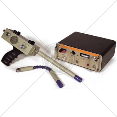
Amplifier Research CL105/106 Shielded Enclosure Leak Detector System

Description

Amplifier Research CL-105/106 provides convenient means of testing the electromagnetic shielding effectiveness at the enclosures most likely points of degradation – the seams, doors and filter connections.

The system consists of a transmitter, receiver, antenna probe, a flex antenna extension, headphones and durable carrying case. The improved sensitivity of the receiver allows it to meet the most rigid MIL standards for shielded room acceptance. The rugged construction yet sleek appearance allows it to be used under the most adverse conditions. The ability to replace the antenna probe shield when worn is also one of the features.

CL-105/CL-160 features a transmitter output of 1 ampere RMS into an inductive load from approximately 5-50 μH and frequency of 95 kHz (crystal controlled). Output signal is pulse modulated at approximately 600 Hz and has a 50% duty cycle. The receiver features two meter scales for high and low operation, aural output for headphone operation, battery operation for portable use and dynamic range of 120dB.

Meter and attenuation dB controls are calibration in logarithmic units. Max. receiver gain is obtained when the attenuation dB control is set at 100. An additional 10 units of attenuation is obtained by rotating the attenuation control in a clockwise direction.

Features

  • Meets MIL Standards for shielded room acceptance
  • Rugged construction
  • Ability to replace antenna worn shield when worn
  • Battery operated

Specifications

Transmitter Output

1 ampere RMS into an inductive load from approximately 5–50 μH

Frequency

95 kHz (crystal controlled)

Output Signal

Pulse modulated at approximately 600 Hz and has a 50% duty cycle

Receiver

Two meter scales for high and low operation Aural output for headphone operation. Battery operated for portable use Dynamic range of 120dB

Meter and attenuation dB controls are calibration in logarithmic units. Maximum receiver gain is obtained when the attenuation dB control is set at 100. An additional 10 units of attenuation is obtained by rotating the attenuation control in a clockwise direction.

Total weight

26 lb

Standards

CISPR
CISPR 11
CISPR 14 - 1
CISPR 14 - 2
CISPR 14 - 2
CISPR 16 - 1
CISPR 16 - 2
CISPR 16 - 3
CISPR 16 - 4
CISPR 22
CISPR 24
IEC
IEC/TR EN 61000 - 1 - 1
IEC/TR EN 61000 - 2 - 1
IEC/TR EN 61000 - 2 - 3
IEC EN 61000 - 3 - 2
IEC EN 61000 - 3 - 4
IEC/TC EN 61000 - 3 - 5
IEC EN 61000 - 4 - 2
IEC EN 61000 - 4 - 3
IEC EN 61000 - 4 - 4
IEC EN 61000 - 4 - 5
IEC EN 61000 - 4 - 6
IEC EN 61000 - 4 - 7
IEC EN 61000 - 4 - 8
IEC EN 61000 - 4 - 9
IEC EN 61000 - 4 - 11
European
EN 50 081 part 1
EN 50 081 part 2
EN 55 011
EN 55 013
EN 55 014
EN 55 015
EN 55 020
EN 55 022
EN 55 024
EN 50 082 part 1
EN 50 082 part 2
EN 50 093
American
FCC Part 15
MIL-STD - 461E