»  Categories   »      Environmental  

image enlarge

AEMC 4620 4-Point Ground Resistance Tester

Description

The rugged 4620 measures from 0 to 2000 Ohms, is auto ranging so it automatically finds the best measurement range, and is easy to use which makes it ideal for maintenance crews performing numerous tests. It exceeds safety and mechanical specifications for drop tests, vibration, and shock as specified in the IEC standards. The 4620 is engineered to reject very high levels of interference, making it ideal for use under harsh conditions such as high stray currents that adversely affect accuracy.

Features

  • Measures soil resistivity with the 4-Point testing method
  • Measures ground resistance with the 2-Point, 3-Point, and Fall of Potential method
  • Step voltage tests
  • Touch potential measurements
  • Auto Ranging
  • Designed to reject high levels of noise interference
  • Very easy to operate just connect, press, and read
  • LED in faceplate alerts the user of fault connections, high auxiliary rod resistance, and high input noise
  • Battery powered
  • Rugged rainproof and dustproof field case
  • Continuity tests on bonding
  • Color coded terminals

 AEMC 4620 Applications

  • 3-point measurements of resistance to ground of grids and ground rods. 3-Point measurements are usually utilized when the grid or electrode can easily be disconnected, if there is suspected corrosion, or circumstances where ground faults are unlikely to occur.
  • Soil resistivity measurements or 4-Point tests. Finding areas of lowest soil resistivity is necessary to achieve a feasible grounding installation solution.
  • 4-point tests
  • Soil resistivity measurements.
  • Touch potential measurements (an alternative to 3-point tests in evaluating electrical safety). This test is preferred when the ground cannot be disconnected, where ground faults are very likely to occur, or when the "footprint" of grounded equipment is comparable to the size of the ground to be tested.

Specifications

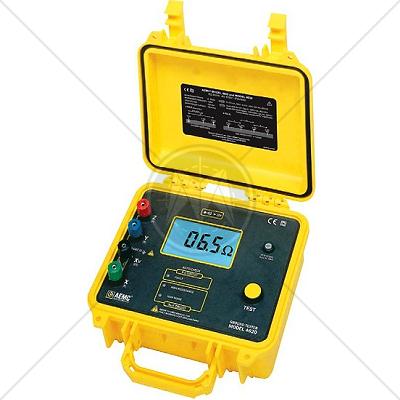
AEMC 4620 Specifications

Measurement Range

Range

20 / 200 / 2000 Watts

Measurement Range

0.00 to 19.99 Watts / 20.0 to 199.9 Watts / 200 to 1999 Watts

Resolution

10mW / 100mW / 1W

Test Current

10 / 1 / 0.1 mA

Accuracy

±2 percent of Reading ± 1ct / ±3 percent of Reading ± 3cts

Auxiliary Electrode Influence

Current Circuit: 200 Watts; Voltage Circuit: 2000 Watts / Current Circuit: 30 kW

Voltage Circuit: 50 kW / Current Circuit: 50 kW; Voltage Circuit: 50 kW

Open Voltage

<42 Volts peak

Resistance Measurement Frequency

128 Hertz square wave

Interference

Rejects high levels of interference voltage (DC, 50 to 60 Hertz, harmonics): DC voltage in series with X: 20 Volts;

AC voltage in series with Y: 13 Volts peak; AC voltage in series with Z: 32 Volts peak

Response Time

Approximately 6 seconds for a stabilized measurement

Voltage Withstand

250 Volts AC with spikes of 3000 Volts AC or 1000 Volts DC

Power Source

8 C cell batteries

Battery Life

1800 15 second measurements

Fuse Protection

0.1 Amp, 250 volts, 0.25 X 1.25 inch; 30 kA Interrupt Capacity

Mechanical Specifications

Display

3-1/2, 0.71 inch (18 millimeters) high; 2000-count; electroluminescent blue backlight - LCD also indicates overrange,

 test lead shorts and lead reversals

Connection

Color coded terminals accept lugs with min. gap of 6 millimeters or standard 4 millimeter banana jacks

LED Indication

3 LEDs indicate high input noise, high auxiliary rod resistance, open leads, blown fuse

Operating Temperature

14 to 131 degrees F (-10 to 55 degrees C), 20 to 90 percent RH

Storage Temperature

-40 to 158 degrees F (-40 to 70 degrees C), 0 to 90 percent RH with batteries removed

Dimensions

9.45 x 7.28 x 4.33 inches

240 x 185 x 110 millimeters

Weight

7.75 pounds (3.5 kg)

Case

Heavy duty o-ring sealed field case

Colors

Case: safety yellow; Front panel: gray

Mechanical Shock

IEC 68-2-27

Vibration Test

IEC 68-2-6

Drop Test

IEC 68-2-32

Dielectric Test

3 kV, 50/60 Hertz, 1 minute between four interconnected measuring terminals and any external metal ground

Environmental

O-ring sealed against dust and water to IP50

Safety Reference Specifications

Safety Ratings

EN 61010-1, Cat. III, Pollution Degree 2, 42 Volts

Agency Approvals

CE Mark


Standards

CISPR
CISPR 11
CISPR 14 - 1
CISPR 14 - 2
CISPR 14 - 2
CISPR 16 - 1
CISPR 16 - 2
CISPR 16 - 3
CISPR 16 - 4
CISPR 22
CISPR 24
IEC
IEC/TR EN 61000 - 1 - 1
IEC/TR EN 61000 - 2 - 1
IEC/TR EN 61000 - 2 - 3
IEC EN 61000 - 3 - 2
IEC EN 61000 - 3 - 4
IEC/TC EN 61000 - 3 - 5
IEC EN 61000 - 4 - 2
IEC EN 61000 - 4 - 3
IEC EN 61000 - 4 - 4
IEC EN 61000 - 4 - 5
IEC EN 61000 - 4 - 6
IEC EN 61000 - 4 - 7
IEC EN 61000 - 4 - 8
IEC EN 61000 - 4 - 9
IEC EN 61000 - 4 - 11
European
EN 50 081 part 1
EN 50 081 part 2
EN 55 011
EN 55 013
EN 55 014
EN 55 015
EN 55 020
EN 55 022
EN 55 024
EN 50 082 part 1
EN 50 082 part 2
EN 50 093
American
FCC Part 15
MIL-STD - 461E