»  Categories   »      High Power Amplifier   »    Amplifier   »    Low Frequency Amplifier  

image enlarge

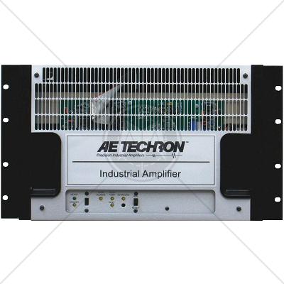
AE Techron 7782HF/HC Power Amplifier DC – 200 kHz 4kW DO-160 Testing

Description

The AE Techron 7782HF/HC amplifier is a DC-enabled unit optimized for high-power, continuous operation into very-low-impedance loads. A single 7782HF/HC can output a 40 mSec pulse with up to 150 amperes peak current. If more current is needed, up to four amplifiers can be combined in parallel and operate as a single system.*

The 7782HF/HC can operate in either voltage or current mode. It provides very low noise and fast slew rates, and can safely drive a wide range of resistive, inductive loads.

Typical use includes as a power source for EMC testing in applications that require both continuous AC or DC signals and significant short term (burst) signals (DO-160, MIL 461, and MIL 704).

Features

  • 7782HF provides over 4,000 watts peak output; 2,858 watts RMS into a 2-ohm load
  • 7782HF/HC delivers 40 mSec pulses of up to 150 amperes peak into a 1-ohm load
  • System output of 800 volts and 70 amperes maximum are possible with multiple, interconnected amplifiers
  • 7782HF provides a frequency bandwidth of DC to 50 kHz at rated power into 8 ohms; DC to 200 kHz at reduced power
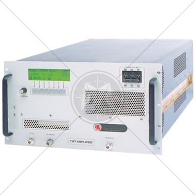
  • Rugged chassis for stand-alone or rack mounted operation. No additional power supplies are required
  • Protection circuitry protects against input overloads, improper output connection (including shorted and improper loads), overtemperature, over-current, and supply voltages that are too high or low
  • Optional “P” versions offer precision control of output offset, DC drift and gain linearity
  • Shipped ready to operate from 208-volt (±10%) three-phase AC mains. Operation from 400-volt (±10%) An AC main is available on request (7782HF version only)

Specifications

AC Specifications

Standard

Ohms

PEAK OUTPUT

RMS OUTPUT

40mSec Pulse, 
30% Duty Cycle

5 Min, 
100% Duty Cycle

1 Hr, 
100% Duty Cycle

5 Min, 
100% Duty Cycle

1 Hr, 
100% Duty Cycle

Volts

Amps

Volts

Amps

Volts

Amps

Volts

Amps

Volts

Amps

Watts

open


0

0

0

0

0

4


120

30

120

30

85

21

85

21

1799

2


120

60

115

58

85

42

81

41

3305

1


80

80

68

68

57

57

48

48

2311

0.5


46

92

44

88

33

65

31

62

1935

Optional High Current (HC) Version

Ohms

PEAK OUTPUT

RMS OUTPUT

40mSec Pulse, 
30% Duty Cycle

5 Min, 
100% Duty Cycle

1 Hr, 
100% Duty Cycle

5 Min, 
100% Duty Cycle

1 Hr, 
100% Duty Cycle

Volts

Amps

Volts

Amps

Volts

Amps

Volts

Amps

Volts

Amps

Watts

2


0

0

0

0

0

1

56

56

55

55


39

39

0

0

0

0.5

42

84

41

82


29

58

0

0

0

0.1

15

150


Input Characteristics

Balanced with Ground

Three terminal barrier block connector 20k ohm differential

Gain

Voltage Mode

20 volts/volt

Current Mode

20 amperes/volt

Residual Noise

Less than 1 millivolt RMS

Slew Rate

40 volts per microsecond

Display, Control, Status

Front Panel

LED Displays indicate

Ready, Standby, High AC Mains, High Temperature, Signal Overload, and Fault conditions in the output stage

Slide Switches for

Run/Standby, LED Indicator Reset

Protection

Over/Under Voltage

± 10% from specified supply voltage amplifier is forced to Standby

Over Current

Breaker protection on both main power and low voltage supplies

Over Temperature

Separate Output transistor, heat sink, and transformer

temperature monitoring and protection

Physical Characteristics

Chassis

All aluminum construction designed for stand-alone or rack-mounted operation; with sliver front panel and

black chassis; the amplifier occupies six EIA 19-inch-wide rack units

Weight

128 lbs. (57.9 kg)

AC Power

Three-phase, 208 VAC ±10%, 47-60 Hz, 20A AC service; 400 VAC ±10%, 47-60 Hz, 10A AC service version available on request

Operating Temperature

10°C to 50°C (50°F to 122°F), Maximum Output Power de-rated above 30°C (86°F)

Humidity

70% or less, non-condensing

Cooling

Internal fans forced air, 300 cfm

Dimensions (W x D x H)

19 in. x 22.37 in. x 10.5 in. (48.3 cm x 56.8 cm x 26.7 cm)

Standards

CISPR
CISPR 11
CISPR 14 - 1
CISPR 14 - 2
CISPR 14 - 2
CISPR 16 - 1
CISPR 16 - 2
CISPR 16 - 3
CISPR 16 - 4
CISPR 22
CISPR 24
IEC
IEC/TR EN 61000 - 1 - 1
IEC/TR EN 61000 - 2 - 1
IEC/TR EN 61000 - 2 - 3
IEC EN 61000 - 3 - 2
IEC EN 61000 - 3 - 4
IEC/TC EN 61000 - 3 - 5
IEC EN 61000 - 4 - 2
IEC EN 61000 - 4 - 3
IEC EN 61000 - 4 - 4
IEC EN 61000 - 4 - 5
IEC EN 61000 - 4 - 6
IEC EN 61000 - 4 - 7
IEC EN 61000 - 4 - 8
IEC EN 61000 - 4 - 9
IEC EN 61000 - 4 - 11
European
EN 50 081 part 1
EN 50 081 part 2
EN 55 011
EN 55 013
EN 55 014
EN 55 015
EN 55 020
EN 55 022
EN 55 024
EN 50 082 part 1
EN 50 082 part 2
EN 50 093
American
FCC Part 15
MIL-STD - 461E